Description
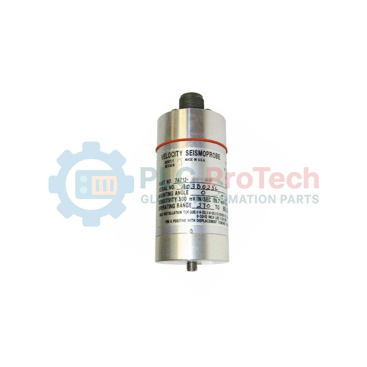
Designed to capture dynamic casing vibration in demanding thermal environments, the Bently Nevada 74712-01-10-03-00 operates as a high-reliability, self-generating velocity transducer. This specialized industrial sensor translates structural physical motion into a proportional two-wire current loop, enabling direct interfacing with diagnostic instruments, distributed control systems (DCS), and continuous machinery protection architectures. By utilizing a self-generating moving-coil design, the unit minimizes active components in high-heat zones, ensuring long-term structural integrity and precise signal fidelity without requiring external power at the point of measurement.
Features
-
High-Temperature Resilience: Engineered to withstand sustained operational temperatures up to 204 degC (400 degF).
-
Two-Wire Interface: Streamlines field wiring requirements by utilizing a robust two-wire current-loop telemetry format.
-
Self-Generating Mechanism: Requires no external excitation power to operate the primary velocity sensing coil.
-
Top-Mount Terminal Block: Provides a simplified connection point that eases field wiring termination and routine maintenance checks.
-
Low-Frequency Optimization: Calibrated with a 4.5 Hz (270 cpm) minimum operating frequency threshold for tracking low-speed machinery dynamics.
Applications
- Casing vibration monitoring on industrial gas turbines and steam turbine housings.
- Continuous predictive maintenance on high-temperature boiler feed pumps and draft fans.
- Mechanical health monitoring of heavy-duty petrochemical process compressors and gearboxes.
- Structural vibration tracking in heat-treatment and primary metal manufacturing facilities.
Ordering Information
| Option Selection |
Option Description |
Configured Specification |
| 01 |
Transducer Mounting Angle & Min Frequency |
0 degrees +/-2.5 degrees, 4.5 Hz (270 cpm) |
| 10 |
Mounting Base Option |
Circular M10x1 thread style |
| 03 |
Connector Option |
Top-mounted terminal block |
| 00 |
Agency Approval Option |
No agency approvals |
Technical Specifications
| Specification Parameter |
Engineering Value |
| Manufacturer |
Bently Nevada |
| Model Number |
74712-01-10-03-00 |
| Product Classification |
High-temperature Two-wire Velocity Transducer |
| Mounting Orientation |
Vertical (0 degrees +/-2.5 degrees) |
| Minimum Operating Frequency |
4.5 Hz (270 cpm) |
| Operating & Storage Temperature |
-29 degC to +204 degC (-20 degF to +400 degF) |
| Casing Diameter |
41 mm (1.6 in) typical |
| Sensor Height |
102 mm (4 in) typical (dependent on terminal block) |
| Net Transducer Weight |
0.48 kg (1.06 lbs) |
| Shipping Weight (Calculated) |
2.00 kg (4.41 lbs) |
| Country of Origin |
United States of America (U.S.A.) |
Empirical Engineering Insights
Alternative Models & Compatibility
The 74712-01-10-03-00 utilizes an "01" mounting option, constraining its measurement path strictly to a vertical orientation (0 degrees +/-2.5 degrees). If horizontal machinery surfaces require monitoring, a different option code must be specified to align the internal spring-mass system with the correct axis of gravity. It functions as a direct field replacement for legacy 74712 units with identical suffix configurations, ensuring seamless mounting footprint integration.
Application Pitfalls & Engineering Notes
Operating near the upper thermal limit of 204 degC requires careful consideration of mechanical cable ratings. Standard PVC-jacketed field wiring will fail rapidly under these conditions; always utilize high-temperature fluoropolymer (PTFE/Teflon) jacketed shielded cables. In high-vibration environments, ensure the M10x1 mounting base is torqued according to OEM specifications to prevent thread loosening and signal attenuation.
Commissioning & Wiring Tips
The top-mounted terminal block (Option 03) simplifies connections but exposes the termination points to ambient airborne contaminants. Use high-integrity industrial conduit or protective terminal covers when deploying in environments with conductive dust or oil mist. Ensure that the shield drain wire is isolated at the sensor head and grounded exclusively at the monitoring system cabinet to prevent artificial ground loops from distorting critical phase or amplitude measurements.
Installation Guidelines
CRITICAL WARNING: SAFETY FIRST
Before beginning mechanical installation or terminal wiring, ensure the target machinery is completely de-energized, locked out, and tagged out (LOTO). Verify that local process temperatures at the mounting point have cooled to a safe handling range to prevent severe thermal burns.
1
Inspect the machinery mounting location, ensuring the surface is machined flat and tapped perpendicular with the correct M10x1 mating threads.
2
Apply a light film of high-temperature anti-seize lubricant strictly to the mounting stud threads, avoiding any excess that could contaminate electrical contact zones.
3
Thread the transducer mounting base manually into the pre-tapped hole. Tighten to the specified installation torque using a calibrated deep-well socket to avoid damaging the sensor's outer casing.
4
Terminate the shielded twisted-pair cabling to the top terminal block. Ensure that lead wire jackets are stripped cleanly without nicking the conductors, and secure the conduit connections to isolate the assembly from structural stress.