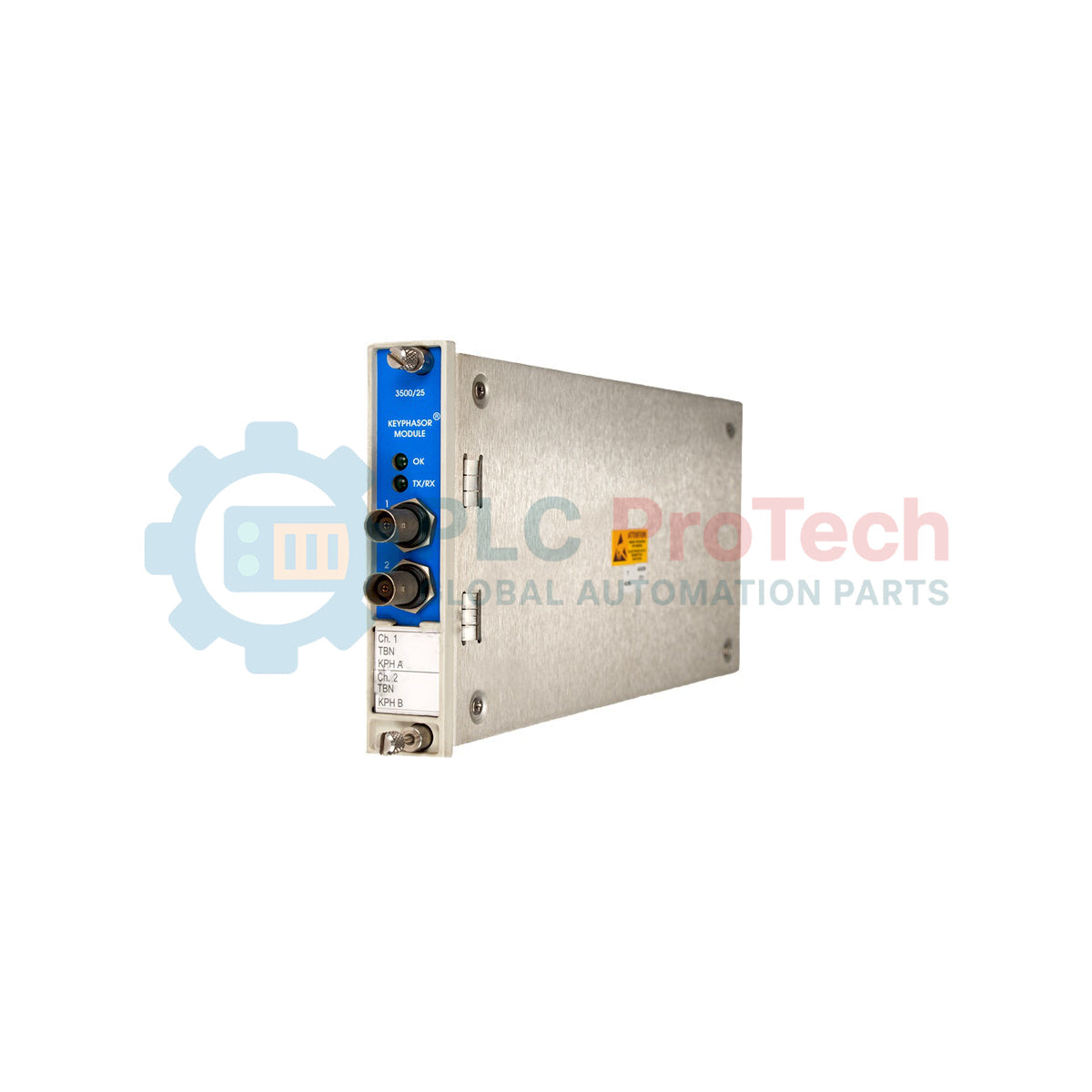
Description
Processing phase-reference and speed signals for machinery diagnostic systems, the Bently Nevada 3500/25-01-02-CN serves as a high-precision, half-height module within the 3500 monitoring platform. This system component conditions pulses from proximity probes or magnetic pickups to determine rotational speed and once-per-turn phase angles, delivering critical reference data directly to the backplane for transient and steady-state machinery analysis. Configured as a single half-height card supporting two channels and paired with an external termination I/O module, this unit integrates seamlessly with local regional standards via its country-specific CN approval path.
Features
- Provides high-accuracy once-per-turn phase reference and rotational speed measurements.
- Supports both magnetic pickups and proximity probe transducers.
- Single half-height card configuration optimization for rack slot conservation.
- External termination interface for versatile, remote wiring management.
- Integrates seamlessly with the 3500 Transient Data Manager (TDM) and key monitoring cards.
- Robust noise immunity and signal conditioning circuit design.
Applications
- Steam turbine and gas turbine rotor speed and phase-angle tracking.
- Turbocompressor and expander startup/shutdown transient profiling.
- Hydroelectric generator shaft alignment and orbit visualization systems.
- Balance-of-plant rotating machinery health monitoring and vector analysis.
Technical Specifications
| Parameter |
Specification Value |
| Manufacturer |
Bently Nevada |
| Model Series |
3500 Series Monitoring System |
| Part Number |
3500/25-01-02-CN |
| Channel Configuration |
01 (Single half-height 2-channel Keyphasor card) |
| I/O Module Type |
02 (I/O Module with External Terminations) |
| Agency Approvals |
CN (Country-specific regional certificates) |
| Input Impedance |
21.8 kOhms (minimum) |
| Signal Range |
+0.8 V to -21.0 V (non-isolated input) |
| Maximum Rotational Speed |
120,000 rpm (sensor and pulse dependant) |
| Country of Origin |
United States (U.S.A.) |
| Shipping Weight (Calculated) |
1.5 kg |
Empirical Engineering Insights
Alternative Models & Compatibility
The Enhanced Keyphasor Module replaces older legacy keyphasor units within standard 3500 racks. It is critical to note that while this enhanced card is backwards compatible with standard backplanes, half-height card pairings must match. You cannot pair an older non-enhanced module in the same vertical slot allocation as an enhanced module.
Application Pitfalls & Engineering Notes
When utilizing option 02 (External Terminations), ensure that the cable length between the external termination block and the rear I/O module does not exceed specified noise margins. High-frequency ambient EMF from neighboring variable speed drives (VSD) can inject signal noise, resulting in false once-per-turn double-triggering or missed pulses.
Commissioning & Wiring Tips
During rack commissioning, configure the threshold voltage and hysteresis parameters within the 3500 Rack Configuration Software to match the specific transducer bias. For a standard 8mm Proximitor, target a trigger threshold that falls precisely in the middle of the physical notch or projection voltage swing to prevent signal dropout during thermal shaft expansion.
Installation Guidelines
CRITICAL WARNING: Prior to module insertion or removal, verify that all power sources to the rack are de-energized or follow verified hot-swap live-insertion procedures if permitted by site safety protocols. Always wear a grounded ESD wrist strap connected to the chassis to prevent catastrophic electrostatic damage to the internal microprocessors.
1
Inspect the module edge connectors and rear I/O pins for physical damage or misalignment prior to insertion.
2
Slide the half-height module firmly into the dedicated rack slot using the card guides until the connector fully seats into the backplane.
3
Tighten the front panel retaining screws to a torque of 1.1 N-m (9.7 in-lb) to secure the unit and establish proper chassis ground pathing.
4
Route the external termination cabling from the rear I/O to the field junction box, ensuring signal lines are properly shielded and grounded at the rack.