Description
Processing dynamic pressure sensor signals to protect rotating machinery against combustion instability, the Bently Nevada 3500/64-01-00 operates as a high-precision four-channel monitor within the 3500 Machinery Protection System. By continuously acquiring and analyzing high-frequency pressure pulsations, this module prevents destructive surge conditions in centrifugal compressors and thermal acoustic stress in gas turbine combustion chambers. The module accepts inputs from dynamic pressure transducers and processes them to generate static and dynamic values, which are compared against user-configured alarm setpoints for real-time protection.
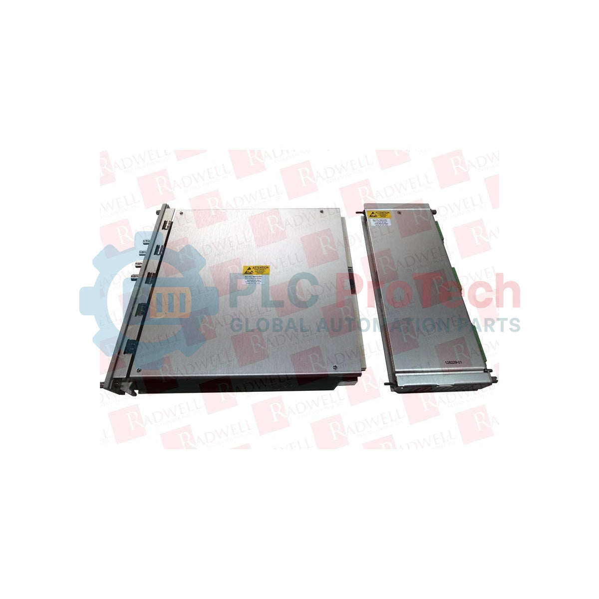
This specific configuration features the 3500/64-01-00 hardware footprint, utilizing an I/O module with internal terminations and standard system approvals. It integrates directly with the 3500 system's backplane, providing continuous machine health monitoring and seamlessly communicating with distributed control systems (DCS) or human-machine interfaces (HMI) via the rack's communications gateway.
Features
-
Four Independent Channels: Delivers concurrent dynamic pressure monitoring across four distinct field locations.
-
Combustion Instability Tracking: Specialized bandpass filtering designed specifically to capture and isolate acoustic combustion dynamics.
-
Configurable Alarms: Individual Alert and Danger setpoints for each channel with adjustable time delays to eliminate nuisance tripping.
-
Internal Terminations: Eliminates the need for external terminal blocks, simplifying control panel wiring layouts.
-
Dynamic Signal Outputs: Buffered transducer outputs on the front panel provide direct access to raw AC signals for external diagnostic analyzers.
Applications
-
Gas Turbine Combustor Protection: Continuous tracking of acoustic resonances and flame instabilities in dry low-NOx (DLN) systems.
-
Centrifugal Compressor Surge Control: Detecting early-stage high-frequency pressure pulsations preceding aerodynamic stall.
-
Hydroelectric Draft Tube Surge: Monitoring low-frequency pressure pulsations caused by vortex ropes in draft tubes.
-
Reciprocating Machinery Diagnostics: Analyzing cylinder pressure variations and valve dynamic behaviors.
Technical Specifications
| Manufacturer |
Bently Nevada (Baker Hughes) |
| Module Part Number |
3500/64-01-00 |
| Monitor Type |
Dynamic Pressure Monitor (4-Channel) |
| I/O Module Option (-01) |
I/O Module with Internal Terminations |
| Approval Option (-00) |
Standard / None (No hazardous area certifications specified for this option code) |
| Input Impedance |
100 kilohms (nominal) |
| Power Consumption |
7.3 Watts typical |
| Signal Resolution |
24-bit Analog-to-Digital (ADC) conversion |
| Operating Temperature |
-30 to +65 Celsius (-22 to +149 Fahrenheit) |
| Country of Origin |
United States |
| Shipping Weight (Calculated) |
2.0 kg (4.4 lbs) |
Empirical Engineering Insights
Alternative Models & Compatibility
The 3500/64-01-00 internal termination design means field wiring lands directly on the terminal blocks on the rear I/O module. If upgrading from older or external termination architectures (like the 3500/64-02-00), the field wiring layout must be verified, as external termination blocks (ETBs) cannot be used with this internal termination variant without completely replacing the rear I/O card.
Application Pitfalls & Engineering Notes
Because this module processes high-frequency dynamic signals, ensure the dynamic pressure transducers utilized match the signal input range (voltage or charge mode configurations in the 3500 Rack Configuration Software). Incorrect transducer selection in software will result in clipping or severely attenuated signal inputs, throwing the monitor into a Not OK status.
Commissioning & Wiring Tips
Always use high-quality shielded, twisted-pair cabling for dynamic pressure inputs. The shields must be grounded strictly at the 3500 rack ground bar (internal terminations provide specific shield terminals). Never ground the shield at both ends, as ground loops will introduce a 50/60 Hz line frequency component that distorts low-frequency pulsation readings.
Installation Guidelines
CRITICAL WARNING
De-energize the entire 3500 rack system prior to inserting or extracting the 3500/64 monitor or rear I/O card. Hot-swapping modules without verified bypass configurations on external shutdown loops can cause accidental machinery trips or damage to internal backplane circuitry.
1
Mount the rear I/O module (internal terminations) into the correct rear chassis slot directly aligned with the intended front slot of the 3500 rack.
2
Slide the main 3500/64 monitor module into the matching front chassis slot, ensuring the card guide rails are fully engaged. Secure the module using the top and bottom captive thumbscrews.
3
Connect the dynamic pressure sensor field cables directly to the terminal strips on the rear I/O card, verifying correct polarities and shield terminations.
4
Power on the rack and connect via the 3500 Rack Configuration Software to configure transducer scale factors, bandpass frequency limits, and alarm levels before placing the unit into service.