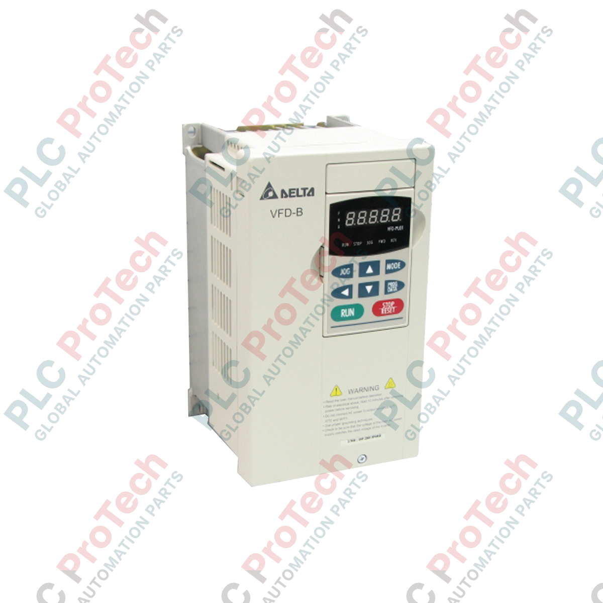
Description
Providing precise speed and torque regulation for three-phase induction motors, the Delta Electronics VFD150B43A operates as a robust 15kW (20HP) vector control drive within the VFD-B series. This modular unit is engineered to manage high-torque demands and continuous industrial duty cycles, operating on 460V three-phase input power. Its integrated dynamic microprocessing core enables micro-step frequency setting adjustments and sophisticated stall prevention algorithms to protect both the drive mechanics and downstream process equipment during load transitions.
Features
-
Precise Frequency Resolution: Delivers high-precision control with a 0.01Hz frequency setting resolution.
-
Overload Endurance: Handles brief operational spikes with a rated overload capacity of 150% of rated current for up to 1 minute.
-
Configurable Skip Frequencies: Avoids mechanical resonance zones via three assignable skip frequency bands adjustable from 0.1 to 400Hz.
-
Robust Stall Prevention: Configurable stall prevention levels from 20% to 250% of the drive's rated current.
-
Active Cooling Architecture: Equipped with an integrated, high-airflow cooling fan to maintain thermal equilibrium in demanding panel configurations.
Applications
- Heavy-duty industrial ventilation fans and air handling units.
- Wastewater treatment facilities and municipal pumping stations.
- Continuous conveyor systems and material handling sortation lines.
- Plastic extrusion machines and packaging line winders.
Technical Specifications Table
| Parameter |
Specification Value |
| Manufacturer |
Delta Electronics |
| Model Number |
VFD150B43A |
| Series Name |
VFD-B Series |
| Power Capacity |
20 HP (15 kW) |
| Voltage Class |
460V AC Three-Phase |
| Frequency Resolution |
0.01Hz |
| Overload Capacity |
150% of rated current for 60 seconds |
| Skip Frequency Range |
0.1 to 400Hz (Three zones programmable) |
| Stall Prevention Limit |
20% to 250% of rated current |
| Cooling System |
Forced-Air Cooling Fan |
| Operating Storage Temp. |
-20 degC to 60 degC |
| Ambient Humidity Limit |
Below 90% RH (non-condensing) |
| Physical Weight |
13 kg |
| Shipping Weight (Calculated) |
15 kg |
Empirical Engineering Insights
Alternative Models & Compatibility
The VFD-B series utilizes a standardized mounting footprint and specific internal register mapping that distinguishes it from newer Delta platforms like the VFD-C2000. When modernizing legacy control systems that leverage serial Modbus communications, review the parameter map addresses directly, as modern drives may require parameter adaptations. Ensure the 'A' designator version firmware aligns with your existing PLC profiles for fieldbus-directed operations.
Application Pitfalls & Engineering Notes
During applications involving high-inertia loads (such as large-diameter industrial fans), decelerating without a dynamic braking resistor can trigger overvoltage (ov) faults. Ensure that parameters for deceleration time (Parameter 01-10/01-12) are sufficiently graduated, or install a correctly sized external dynamic braking unit to dissipate regenerative energy. Maintain clear vertical space around the drive’s fan-cooled intake and exhaust vents to prevent thermal trips in high-density electrical cabinets.
Commissioning & Wiring Tips
Always route control and analog signal wiring through separate, grounded metallic conduits away from the main power feed lines (R, S, T) and motor output lines (U, V, W) to prevent electromagnetic interference (EMI) from disrupting the analog inputs. To maintain the 0.01Hz resolution stability, ground the shield of your analog control cable only at the drive end using a dedicated low-impedance grounding bar.
Installation Guidelines
CRITICAL WARNING: Hazardous voltage levels remain active inside the drive capacitors even after the mains power supply is isolated. Wait a minimum of 10 minutes following complete physical de-energization and confirm that the internal DC bus voltage has dropped below 36V DC using a certified digital multimeter before touching terminal connections or starting diagnostic work.
1
Mount the drive vertically on a flat, non-flammable back panel to optimize airflow and natural thermal dissipation.
2
Connect the primary three-phase utility input to terminals R, S, and T, and connect the motor feed cables directly to terminals U, V, and W.
3
Execute a cold-wire insulation test on the motor cables prior to terminal termination; never perform a megger test directly on the drive power terminals.
4
Perform an initial low-voltage verification check on the auxiliary control terminals before energizing the high-voltage 460V input.