Description
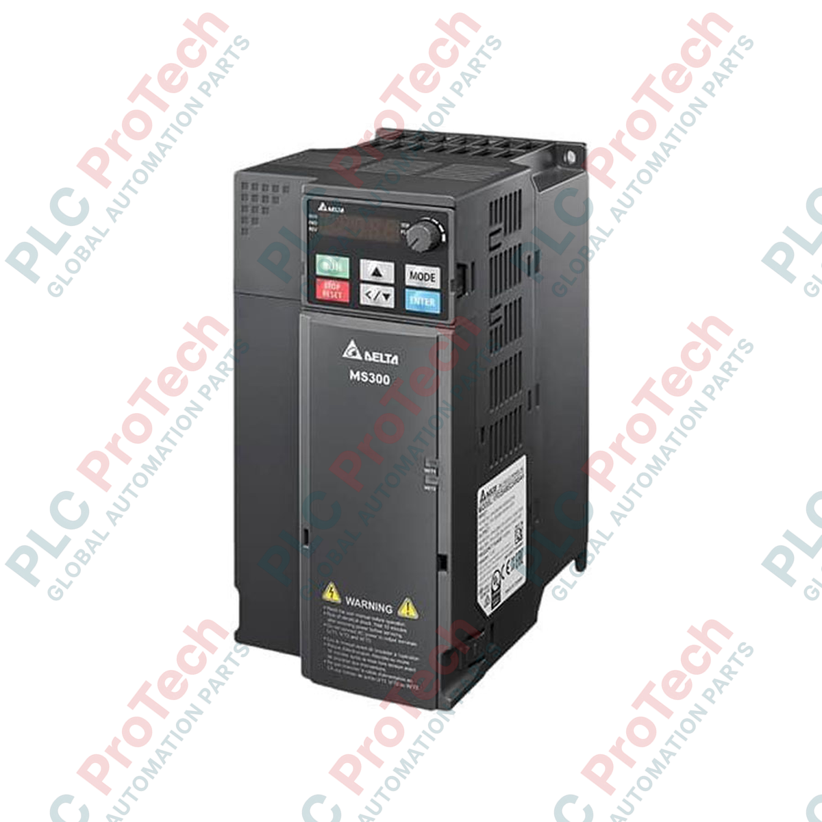
Engineered to deliver high-performance vector control in complex industrial environments, the Delta Electronics VFD45AMS43ANSAA belongs to the compact, versatile MS300 Series micro-drive family. This drive is optimized for demanding applications requiring robust motor control, featuring a 45A rated output current under Heavy Duty operation and an integrated Safe Torque Off (STO) safety function to meet strict global safety requirements. Built with a space-saving design, it seamlessly supports both induction and permanent magnet motors while operating on a 460V 3-phase input power supply.
Key Features
-
Heavy Duty Overload Capacity: Rated for a 45A output current with an overload tolerance of 150% for 60 seconds.
-
Advanced Safety Integration: Built-in Safe Torque Off (STO) complying with EN ISO 13849-1 Cat 3 PL e and IEC 61508 SIL3.
-
Flexible Motor Support: Dual-control capability allows open-loop control of both traditional Induction Motors (IM) and high-efficiency Permanent Magnet (PM) synchronous motors.
-
Compact Book-Shelf Design: Standard IP20 housing allows side-by-side DIN-rail mounting to maximize control cabinet space.
-
Built-in USB Port: Facilitates direct connection to PCs for rapid configuration, commissioning, and diagnostic monitoring using Delta software.
Applications
- High-torque machine tool spindles and metal processing hardware.
- Industrial packaging machinery, sorting conveyors, and logistics handling.
- Heavy-duty pumping systems and high-volume HVAC air handling units.
- Precision textile production systems and automated woodworking machinery.
Technical Specifications
| Parameter |
Value |
| Manufacturer |
Delta Electronics |
| Model Number |
VFD45AMS43ANSAA |
| Series |
MS300 (Standard Micro Drive) |
| Rated Input Voltage |
460V AC (3-Phase) |
| Rated Output Current |
45A (Heavy Duty, 150% overload for 60 seconds) |
| Enclosure Rating |
IP20 (Standard Housing) |
| Integrated EMC Filter |
None (No Function Code: N) |
| Safety Standard |
Built-in STO (SIL3 / PL e) |
| Control Modes |
V/F, SVC (Sensorless Vector Control) for both IM and PM |
| Physical Unit Weight |
6.25 kg |
| Shipping Weight (Calculated) |
8.00 kg |
Connections and Interfaces
| Terminal Block Designation |
Functional Assignment / Description |
| R/L1 - S/L2 - T/L3 |
3-Phase AC power supply input terminals |
| U/T1 - V/T2 - W/T3 |
AC motor output terminals (Induction or PM) |
| +1 - +2 / B1 - B2 |
Connections for DC reactor and external dynamic braking resistors |
| STO1 - STO2 - DCM |
Dual-channel Safe Torque Off inputs and signal common |
| RA - RB - RC |
Multi-function relay output (Form C) |
Alternative Models & Compatibility
When upgrading older Delta VFD-E or VFD-M series drives to the modern MS300 series, verify physical cabinet mounting constraints since the MS300 is significantly narrower. Parameter files can be migrated through Delta VFDSoft, but auto-tuning should be re-executed on the MS300 platform to ensure the sensorless vector algorithms accurately map the winding resistance of older motors.
Application Pitfalls & Engineering Notes
Because this is the "N" designated model, it lacks a built-in EMC filter. If you are operating this drive in environments with sensitive instrumentation, digital load cells, or high-speed serial communications, you must install an external line filter on the input side and use fully shielded motor cables to mitigate high-frequency electromagnetic noise. Ensure the carrier frequency parameter is adjusted appropriately to maintain low thermal load inside sealed non-ventilated enclosures.
Commissioning & Wiring Tips
During initial commissioning, if the drive is not wired to an external emergency safety relay, the STO1 and STO2 terminals must be jumpered to the common reference (+24V / DCM) using the factory-provided shorting clips. Leaving these terminals open will cause the drive to display continuous safety fault states (STL1 or STL2) and block output power initialization. Ground the motor shield directly to the drive's chassis ground lug to prevent ground-loop current injection.
Installation Guidelines
CRITICAL WARNING: Prior to undertaking any physical wiring or terminal alterations, disconnect all primary supply power. Allow a minimum of 10 minutes for internal DC bus capacitors to discharge fully. Use a calibrated multimeter to confirm that voltage between the + and - terminals is under 36V DC before commencing work.
1
Mount the variable frequency drive vertically on a flat, vibration-free surface, maintaining a minimum of 50mm clearance above and below the cooling fan housing to ensure unobstructed convection airflow.
2
Verify that the source supply voltage aligns strictly with the 460V AC 3-phase input requirements. Connect input power to R/L1, S/L2, and T/L3 terminals using correctly sized copper conductors rated for at least 75 degC.
3
Connect the motor leads to terminals U/T1, V/T2, and W/T3. Do not apply main AC power to these output terminals, as this will result in immediate catastrophic failure of the drive's internal IGBT power bridge.