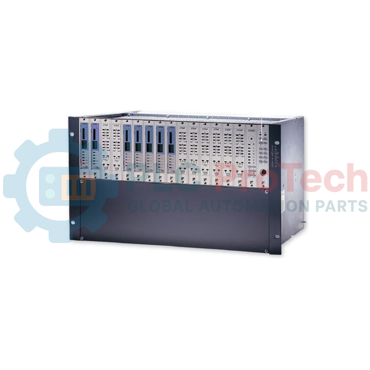
Description
Serving as the structural and electrical backbone for industrial gas detection networks, the Honeywell 05701-A-0516 accommodates up to eight System 57 control cards in a secure, rack-mountable chassis. This sub-rack houses the passive backplane interface, enabling direct point-to-point connections between external field sensors, power distribution systems, and dedicated control modules. Engineered for high-density environments, its robust structural design ensures long-term physical integrity and reliable electrical contact pins, minimizing signal degradation under typical industrial vibration and thermal cycling conditions.
Features
-
8-Channel Card Capacity: Dedicated slots support up to eight System 57 gas or flame control cards in a space-saving configuration.
-
Integrated Backplane Routing: Hardwired backplane paths eliminate the need for complex internal wiring harnesses, reducing potential points of failure.
-
Heavy-Duty Construction: Zinc-plated steel and anodized aluminum components shield installed cards from physical damage and ambient electromagnetic interference.
-
Modular Serviceability: Allows for rapid hot-swapping or physical replacement of individual control cards without disturbing adjacent channel wiring.
Applications
- Multi-channel toxic and combustible gas monitoring enclosures.
- Petrochemical processing sites and refinery control rooms.
- Offshore oil and gas platforms requiring compact instrument panels.
- Wastewater treatment facility gas detection systems.
Technical Specifications
| Manufacturer |
Honeywell |
| Model Number |
05701-A-0516 |
| System Series |
System 57 |
| Module Capacity |
8 control card slots |
| Mounting Profile |
3U height, half-width profile |
| Operating Temperature |
-10 to +50 degC |
| Storage Temperature |
-25 to +55 degC |
| Humidity Limits |
0 to 90% RH, non-condensing |
| Shipping Weight (Calculated) |
2.0 kg |
Connections and Interfaces
| Connection Group |
Function / Circuit Assignment |
| DC Power Input |
Dual terminal blocks for primary and secondary redundant DC supply lines. |
| Individual Card Backplane |
Dedicated multi-pin connectors for matching 5701 control card edge interfaces. |
| Earth Ground Stud |
Heavy-duty M5 grounding post for panel and cable shield drain wire termination. |
Empirical Engineering Insights
Alternative Models & Compatibility
The 05701-A-0516 is a half-width 8-way sub-rack, offering a highly compact alternative to the full-width 16-way 05701-A-0502 sub-rack. Ensure that mechanical keying pins on the passive backplane are configured correctly prior to card insertion, as inserting a card into a slot keyed for a different sensor type can damage the internal backplane traces.
Application Pitfalls & Engineering Notes
When configuring a fully populated 8-way sub-rack, calculate the combined maximum current draw of all cards under alarm states (when relay coils are energized and sensor currents peak) to size the external power supply properly. Do not block natural convective airflow; provide at least 50mm of clear space above and below the chassis in enclosed cabinets to prevent thermal accumulation.
Commissioning & Wiring Tips
Ensure the sub-rack chassis ground stud is bonded directly to the main instrument clean earth bar with low-impedance copper conductors. For analogue sensor wiring, run shielded twisted-pair cables and terminate the shields only at the sub-rack end to prevent disruptive ground loops.
Installation Guidelines
CRITICAL SAFETY WARNING
Isolate and lock out all power sources before mounting or wiring the sub-rack. Do not insert or remove control cards while the backplane is energized. Failure to comply can cause electrical arcing, damage sensitive solid-state components, and trigger accidental system alarms.
1
Mount the sub-rack securely in a standard 19-inch cabinet panel or bracket layout using M6 hardware.
2
Connect a dedicated low-impedance ground cable from the sub-rack earth stud to the system's clean earth bar.
3
Wire the DC supply sources to the backplane power terminals, checking line polarities before applying voltage.
4
Install the cards into their designated card guides, ensuring clean engagement with the backplane connectors.