Description
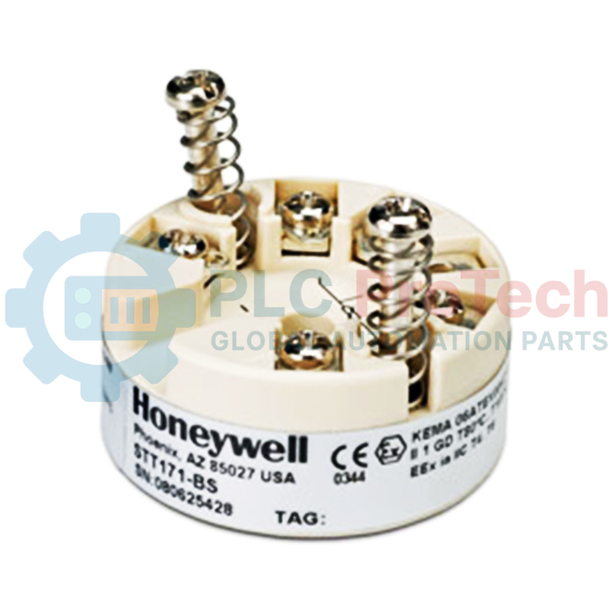
Process automation systems rely on the Honeywell STT17H-00-0-00R-00E-D00-00 headmount temperature transmitter to convert low-level sensor inputs into stable control-level signals. This DIN Form B compatible unit functions as a high-performance signal converter, accepting RTD, thermocouple, resistance, and millivolt sensor configurations. Utilizing dual-sensor input capabilities, it supports differential or average temperature monitoring while ensuring complete galvanic isolation to protect downstream PLC and DCS components from ground loop noise and common-mode voltage transients.
Key Features
-
HART Protocol Integration: Supports HART communications overlayed on a standard 4-20 mA analog output loop, enabling remote calibration and diagnostics.
-
Universal Input Versatility: Direct interface compatibility with standard RTD, thermocouple (T/C), linear resistance (Ohm), and millivolt (mV) inputs.
-
Dual-Sensor Calculations: Configurable for single or dual sensor inputs to execute difference or average calculations in critical process points.
-
HART Multidrop Capabilities: Enables multi-device digital network layouts over a single twisted-pair wire run.
-
NAMUR NE43 Compliance: Provides deterministic sensor error response profiles to ensure field safety and predictive diagnostic coverage.
-
Galvanic Isolation: Heavy-duty electrical isolation between input stage and loop circuit prevents noise propagation.
Industrial Applications
- Petrochemical and chemical processing temperature monitoring loops.
- Power generation steam temperatures and bearing monitoring.
- Refinery column differential temperature thermal profiling.
- Heavy industrial OEM machinery and heat treatment systems.
Technical Specifications
| Manufacturer |
Honeywell |
| Model Number |
STT17H-00-0-00R-00E-D00-00 |
| Output Signal |
4-20 mA analog with HART digital communication |
| Sensor Input Options |
RTD, Thermocouple, Resistance (Ohm), millivolt (mV) |
| Input Configuration |
Single or Dual (difference or average calculation) |
| Mechanical Mounting |
DIN Form B headmount configuration |
| Error Fault Signaling |
NAMUR NE43 user-configurable limits |
| Isolation Protection |
Galvanically isolated input/output circuit |
| Configuration Methods |
STT17C PC Configuration Tool or compatible HART Handheld Terminal |
| Shipping Weight |
1.3 kg |
Empirical Engineering Insights
Alternative Models & Compatibility
The STT17H is the HART-enabled variant in the STT17 family, distinguishing itself from the basic STT171 (which offers simple 4-20 mA output with PC-only configuration) and the STT173 (which provides Foundation Fieldbus protocol options). When replacing older legacy Honeywell transmitters, ensure that your existing DCS integration blocks or handheld field communicators are loaded with the correct Device Description (DD) file for the STT17H family to allow parameter mapping.
Application Pitfalls & Engineering Notes
When configuring a dual-sensor application (e.g., differential or redundant tracking), utilize non-grounded thermocouple configurations. If grounded thermocouples are installed in a dual-sensor layout, ground loops can form across the shared sensor terminal block, degrading measurement linearity. In environments with heavy high-frequency noise from nearby variable speed drives, ensure that sensor input leads remain as short as possible within the Form B junction head.
Commissioning & Wiring Tips
When connecting the PC-based STT17C configuration tool, a loop resistance of at least 250 Ohms is strictly required between the transmitter and the interface modem. Attempting to program the device without this inline resistance will result in intermittent or failed HART communication. Ensure all field wiring uses twisted-pair, shielded cables grounded exclusively at the control panel end to avoid ground-potential differences.
Installation Guidelines
CRITICAL SAFETY WARNING
Isolate and completely de-energize the instrument loop power supply prior to opening the junction box cover or disconnecting any signal terminals. Working on live instrument loops in hazardous processing areas can trigger explosive atmospheres or damage delicate control inputs.
1
Mount the STT17H unit securely inside the DIN Form B head closure using the provided screw brackets, taking care not to pinch internal wires.
2
Connect the physical sensor inputs to the corresponding designated terminal screws, ensuring compliance with the chosen RTD or thermocouple wiring topology.
3
Connect the positive (+) and negative (-) 4-20 mA loop wires, verifying polarity match with the analog input channel of your controller.
4
Fasten all housing screws to ensure internal moisture protection before re-applying main loop voltage.