Description
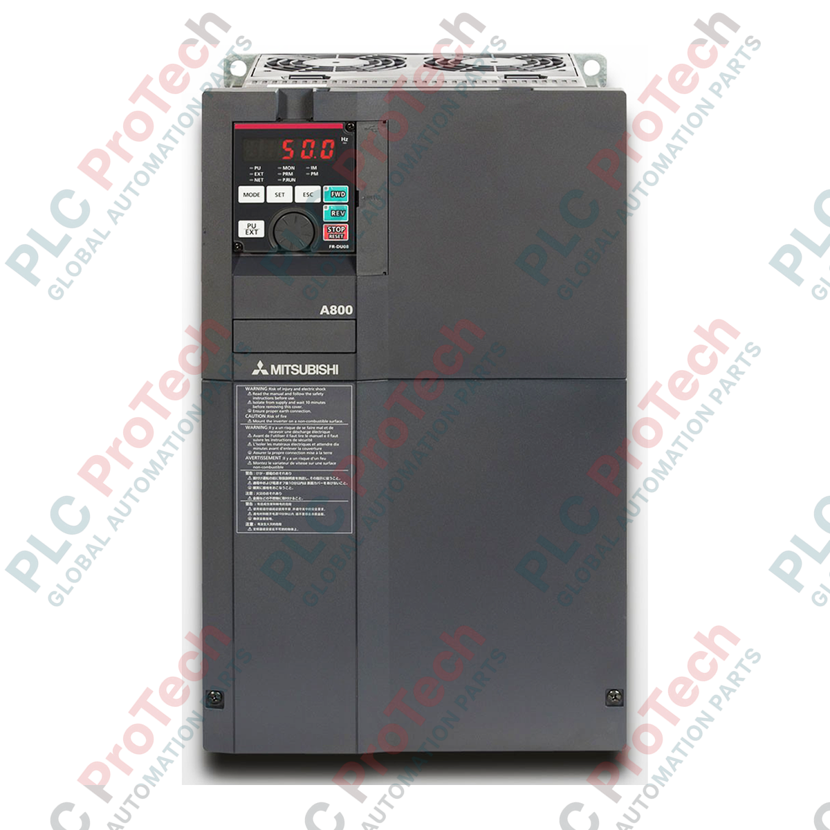
Engineered for high-demand industrial speed and torque applications, the Mitsubishi Electric FR-A840-00250-2-60 is a premium FR-A800 Series variable frequency drive operating in the 400V voltage class. This standard-model inverter features specialized circuit board protective coating compliant with 3C2 specifications (without plated conductors) to ensure long-term reliability in corrosive, humid, or dusty environments. It supports advanced vector control methods to deliver precise motor dynamics for heavy-duty applications like cranes, extruders, and ventilation systems.
Key Features
-
Conformal PCB Coating: Engineered with standard 3C2-rated circuit board coating to withstand high moisture, chemical exposure, and particulate accumulation.
-
Advanced Vector Control: Supports real sensorless vector control and closed-loop vector control for absolute torque precision down to zero speed.
-
Dual Rating Capability: Optimizes sizing by allowing selection between Super Light Duty (SLD), Light Duty (LD), Normal Duty (ND), and Heavy Duty (HD) profiles.
-
Built-in PLC Functionality: Program internal logic using Mitsubishi Electric developer software to manage local I/O without an external controller.
-
Comprehensive Safety: Integrated safe torque off (STO) safety terminals comply with SIL 2 / PL d standards.
Applications
-
Material Handling: Dynamic hoist control, crane gantry synchronization, and heavy-duty conveyor systems requiring high starting torque.
-
Process Pumps & Compressors: Variable flow management under fluctuating load profiles in chemical processing and water treatment facilities.
-
Extruders and Mixers: High-inertia load management with precise speed holding under varying material viscosity.
-
Metalworking and Tensioning: Precise torque limitation and winding/unwinding control loops.
Technical Specifications
| Parameter |
Specification |
| Manufacturer |
Mitsubishi Electric |
| Model Code |
FR-A840-00250-2-60 |
| Series |
FR-A800 |
| Voltage Class |
400 V Class (3-phase 380 to 500 V AC, 50Hz/60Hz) |
| SLD Rated Current |
25.0 A |
| Control Method |
V/F Control, Advanced Magnetic Flux Vector, Real Sensorless Vector |
| PCB Coating Type |
Conformally Coated (Class 3C2), without plated conductor (-60) |
| Enclosure Rating |
IP20 (Open Type) |
| Operating Temperature |
-10 degC to 50 degC (non-freezing) |
| Device Net Weight |
6.7 kg |
| Shipping Weight (Calculated) |
9.0 kg |
Control Terminals & Wiring Assignments
| Terminal Symbol |
Terminal Name |
Functional Description |
| STF |
Forward Rotation Start |
Turn ON STF to start forward rotation; turn OFF to decelerate and stop. |
| STR |
Reverse Rotation Start |
Turn ON STR to start reverse rotation; turn OFF to decelerate and stop. |
| SD |
Contact Input Common |
Common terminal for contact input signals (sink logic standard). |
| 10 |
Frequency Setting Power Supply |
DC 10V output for analog speed reference potentiometers. |
| 2 |
Frequency Setting (Voltage) |
DC 0 to 5V or 0 to 10V analog speed command input. |
| 4 |
Frequency Setting (Current) |
4 to 20 mA DC analog speed command input. |
Empirical Engineering Insights
Alternative Models & Compatibility
The FR-A840-00250-2-60 is directly backward compatible with older FR-A740-00250-EC installations. Users migrating to the FR-A800 series must utilize FR Configurator2 to convert parameter settings, ensuring torque boost and motor tuning values map correctly to the updated algorithm structure.
Application Pitfalls & Engineering Notes
When utilizing this inverter in closed cabinets, account for the 6.7 kg thermal footprint. Adequate airflow clearance must be maintained: 5 cm on both sides and 10 cm above/below the unit. Operating in temperatures exceeding 40 degC requires carrier frequency derating via Parameter 72 to prevent overtemperature tripping (E.THT or E.FIN).
Commissioning & Wiring Tips
Ensure that all analog control signals (terminals 2, 4, and 10) are wired with shielded, twisted-pair cables. Ground the shield exclusively at the drive-end SD terminal to prevent ground loops. Never route motor output leads (U, V, W) in the same conduit as control or communications cables.
Installation Guidelines
CRITICAL WARNING: Ensure main input line power (R/L1, S/L2, T/L3) is completely de-energized and locked out before attempting installation or maintenance. Wait a minimum of 10 minutes post-power-down for the DC bus capacitors to discharge. Verify the DC voltage across terminals P/+ and N/- is below 30V using a calibrated digital multimeter before handling terminals.
1
Mount the inverter vertically to a flat, rigid metal backplate to ensure optimal heat dissipation and grounding path efficiency.
2
Connect the protective earth (PE) terminal to the system ground busbar using low-impedance braided strap or green-and-yellow grounding conductor.
3
Wire the three-phase AC input to R/L1, S/L2, T/L3, and connect the motor leads to U, V, and W. Do not install a power factor correction capacitor on the output side.
4
Establish control wiring loop via standard sink logic or switch to source logic configuration utilizing the internal jumper block as specified by system drawings.