Description
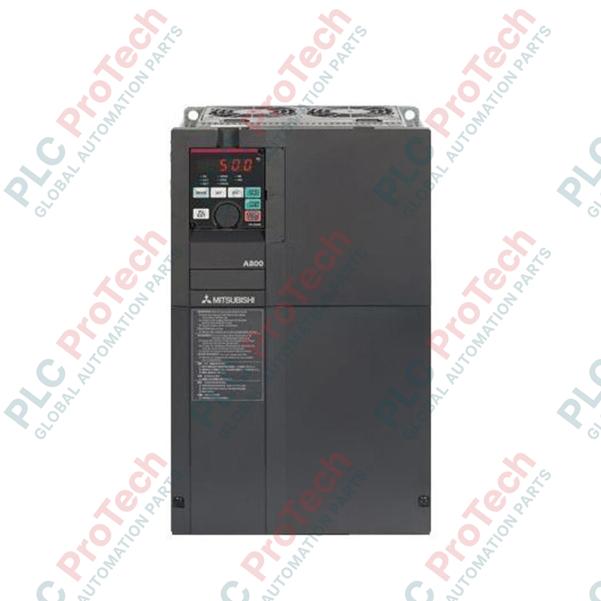
Designed for heavy industrial applications requiring exceptional motor control torque and reliability, the Mitsubishi Electric FR-A840-04810-2-60 is a high-capacity variable frequency drive within the premium FR-A800 inverter family. This 400V class inverter delivers precise vector, sensorless, and V/f control for highly demanding automation loops. It is engineered with a Class 3C2 conformal board coating for superior resistance against chemical and gaseous environmental hazards, making it ideal for deployment in harsh industrial settings. It features multiple overload ratings, allowing optimization for Super Light Duty (SLD) configurations up to a rated current of 481 A.
Features
-
Real Sensorless Vector Control: Achieves high-torque and fast response times without requiring an encoder feedback interface.
-
Enhanced Environmental Protection: Conformal coating (3C2 classification) on all internal printed circuit boards protects sensitive electronics from moisture, dust, and corrosive industrial gases.
-
Multi-Rating Capability: Seamless adjustment between Super Light Duty (SLD), Light Duty (LD), Normal Duty (ND), and Heavy Duty (HD) output profiles.
-
Integrated Safety Protocols: Built-in dual-channel Safe Torque Off (STO) capability for compliance with global functional safety regulations.
-
Advanced Connectivity: Built-in USB diagnostic port and support for multiple industrial Ethernet and fieldbus communication options.
Applications
- Municipal wastewater aeration compressors and high-volume water pump systems.
- Industrial manufacturing extruders, mixers, and continuous-run process machinery.
- Metal processing rolling mills, wire drawing lines, and heavy material handling cranes.
- Mining ventilation fans, large belt conveyor drives, and bulk material stackers.
Technical Specifications
| Parameter |
Specification |
| Manufacturer |
Mitsubishi Electric |
| Model Identifier |
FR-A840-04810-2-60 |
| Product Series |
FR-A800 Series |
| Voltage Class |
400 V Class (Three-Phase 380 to 500 VAC, 50/60 Hz) |
| SLD Rated Inverter Current |
481 A |
| Control Logic Variant |
CA Type (European layout standard) |
| Circuit Board Coating |
With (Conforms to IEC 60721-3-3 Class 3C2) |
| Plated Conductor |
Without |
| Enclosure Rating |
IP00 (Open Type) |
| Cooling Mechanism |
Forced Air Cooling |
| Actual Unit Weight |
120.0 kg |
Connections and Interfaces
| Terminal Group |
Functional Assignment / Description |
| R/L1, S/L2, T/L3 |
Main three-phase AC power supply input connections. |
| U, V, W |
Three-phase AC variable frequency output terminals to the induction or PM motor. |
| P/+, N/- |
DC link common bus terminals for connecting external braking units or regeneration modules. |
| S1, S2, SC |
Safety circuit input connections for redundant dual-channel STO (Safe Torque Off) shutdown loops. |
Alternative Models & Compatibility
The FR-A840-04810-2-60 can directly upgrade older generation FR-A740-04810 series units. Note that control terminal layouts differ slightly: the "-2-60" represents a standard European control terminal structure, which may require minor wiring layout adjustments compared to Japanese native models (-1-60). Parameter conversion can be fully completed using Mitsubishi's FR Configurator2 software, although complex multi-speed and custom PID parameters should be audited manually post-migration.
Application Pitfalls & Engineering Notes
Due to the unit’s substantial weight (120 kg) and heat dissipation requirements under high load conditions, vertical mounting inside a robust, well-ventilated enclosure is mandatory. When designing cabinet ventilation, ensure the cabinet can evacuate the heavy thermal load produced by the drive at its nominal 481 A current rating. Avoid placing other heat-generating equipment directly below the inverter intake vents.
Commissioning & Wiring Tips
To prevent electrical noise issues on sensitive analog feedback lines, use shielded twisted pair (STP) cabling for all control-circuit inputs and ensure the shield is grounded only at the drive end. If the Safe Torque Off (STO) terminals (S1, S2, and SC) are not wired to an external emergency safety relay, the pre-installed shorting link blocks must remain in place; otherwise, the inverter will display an "E.SAF" alarm and refuse to run.
Installation Guidelines
CRITICAL WARNING
Ensure that the main incoming AC power source is fully de-energized, locked, and tagged out before removing the terminal cover plate. Wait at least 20 minutes for internal high-voltage capacitors to bleed down. Verify zero voltage across terminals P/+ and N/- with a reliable voltmeter before commencing terminal wiring.
1
Mount the heavy IP00 chassis vertically onto a flat, non-combustible steel surface using the specified mounting bolts.
2
Verify grounding connections are correctly established back to the main factory earth PE busbar using the shortest possible cable paths.
3
Tighten main terminal block power connections (R/L1, S/L2, T/L3 and U, V, W) using a calibrated torque wrench to the exact torque specifications detailed in the OEM manual to prevent hot-spot connections.