Description
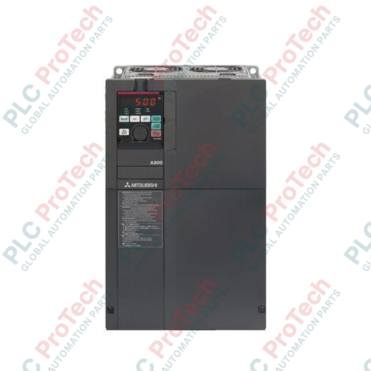
Executing high-capacity motor control in demanding industrial environments, the Mitsubishi Electric FR-A840-06100-2-60 is a high-performance variable frequency drive designed for the FR-A800 series architecture. This 400V class inverter is engineered with a Super Light Duty (SLD) rating of 610A, making it highly suitable for large-scale pumps, fans, and heavy-duty industrial machinery. The unit features built-in protective circuit board coating (3C2) to resist atmospheric contaminants and humidity, ensuring long-term operational reliability in harsh industrial conditions. It is configured as a standard model without plated conductors, prioritizing robust electrical performance and structural integrity in centralized motor control centers.
Features
-
High-Capacity Power Output: Designed for 400V class systems with a high Super Light Duty (SLD) current rating.
-
Environmental Protection: Standard configuration includes 3C2 class conformal circuit board coating to guard against corrosion, dust, and humidity.
-
Advanced Vector Control: Supports real sensorless vector control and vector control with encoder feedback for precise speed and torque regulation.
-
Built-in Safety & Functionality: Integrated safety stop functions (STO) conforming to ISO 13849-1 PLd/Cat.3 and SIL2 standards.
-
Optimized Thermal Design: Heat dissipation system engineered for large-scale electrical panel integration.
Applications
- High-volume municipal and industrial water pumping systems.
- Large-scale HVAC supply and exhaust ventilation fans.
- Industrial air compressors and gas blower installations.
- Conveyor systems and bulk material handling equipment in mining or cement processing.
Technical Specifications
| Parameter |
Specification Value |
| Manufacturer |
Mitsubishi Electric |
| Model Code |
FR-A840-06100-2-60 |
| Series |
FR-A800 |
| Voltage Class |
400V Class (Three-Phase Input) |
| SLD Rated Current |
610 A |
| Conformal Coating |
Yes (IEC 60721-3-3 3C2 compliant) |
| Plated Conductor |
Without |
| Structure / Type |
Standard Model (-2) / CA Type |
| Shipping Weight |
170 kg |
Alternative Models & Compatibility
This model replaces older FR-A740 series configurations of equivalent capacity. When migrating from the A700 series, verify panel mounting dimensions and control terminal wiring differences. Parameter configurations can be imported and converted using the FR-Configurator2 software utility to maintain application logic compatibility.
Application Pitfalls & Engineering Notes
With a high unit weight of 170 kg, mechanical installation requires dedicated lifting lugs and structures rated for the load. Ensure the installation enclosure is designed for the high thermal dissipation profile of a 610A SLD drive. Maintain standard clearance guidelines above and below the drive to facilitate proper airflow through the cooling heatsinks. Do not block the intake or exhaust paths.
Commissioning & Wiring Tips
Always use symmetrical, shielded motor cables to prevent electromagnetic interference (EMI) issues with nearby low-voltage instrument signals. Connect the grounding terminals directly to the system's common ground busbar using short, heavy-gauge cables. Prior to initial power-up, verify that the motor thermal overload parameter (Pr. 9) is matched to the actual connected motor nameplate full-load current to prevent motor damage during high-load operations.
Installation Guidelines
CRITICAL WARNING
Risk of electrical shock or arc flash. Disconnect and lock out all input power sources prior to starting installation, wiring, or maintenance procedures. After power is disconnected, wait at least 10 minutes for the internal bus capacitors to discharge fully, and verify zero voltage on the DC bus terminals before touching any internal electrical connections.
1
Mount the inverter vertically on a flat, non-flammable surface inside a dust-free, well-ventilated enclosure.
2
Connect the primary three-phase AC input lines to power input terminals R/L1, S/L2, and T/L3.
3
Route shielded motor power cables from output terminals U, V, and W to the motor, ensuring the shield is grounded at the drive side.
4
Verify proper connection of safety circuit wiring (STO) or configure jump linkages if internal safety functions are managed by an external safety relay.