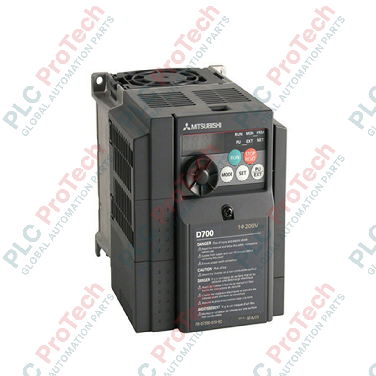
Description
Managing motor speed and torque requirements in demanding industrial configurations, the Mitsubishi Electric FR-D720-5.5K acts as a high-reliability compact micro-drive within the FR-D700 Series. Engineered for three-phase 200V applications, this 5.5 kW digital inverter provides exceptional motor control accuracy through advanced magnetic flux vector control, making it ideal for packaging, conveying, and processing machinery. Its ultra-compact footprint supports side-by-side mounting to maximize control cabinet space efficiency, while integrated Modbus RTU communications ensure seamless integration into factory automation networks.
Features
-
Magnetic Flux Vector Control: Achieves reliable starting torque of 150% at ultra-low speeds (1 Hz) for heavy startup loads.
-
Integrated Safety Stop: Features emergency stop capabilities compliant with EN ISO 13849-1 Category 3 / PLd for reliable machine interlocks.
-
Modbus RTU Built-in: Control and monitor drive parameters over a standard RS-485 serial network via the integrated RJ45 interface.
-
Spring Clamp Control Terminals: High-reliability vibration-proof wiring connections that reduce commissioning times.
-
Energy Saving Mode: Advanced excitation control dynamically optimizes motor current relative to load demand.
Applications
-
Conveyor Systems: Precise acceleration and deceleration control for material handling lines.
-
Pumps and Fans: Flow regulation and energy optimization in HVAC and cooling loops.
-
Packaging Equipment: Variable speed drive control for continuous feed and wrapping systems.
-
Machine Tools: Spindle and feeder speed management for automated production machinery.
Technical Specifications Table
| Specification Parameter |
Value / Rating |
| Manufacturer |
Mitsubishi Electric |
| Model Number |
FR-D720-5.5K |
| Series Name |
FR-D700 Series (FR-D720) |
| Input Voltage Class |
Three-phase 200V to 240V AC, 50/60 Hz |
| Inverter Capacity |
5.5 kW (7.5 HP) |
| Output Current Rating |
24.0 A |
| Control Scheme |
V/F Control, General-Purpose Magnetic Flux Vector Control |
| Enclosure Class |
IP20 (Open Type) |
| Communication Port |
RS-485 (Modbus RTU / PU Connector) |
| Recommended MCCB Rating |
50A (Without Reactor) / 40A (With Reactor) |
| Compatible Magnetic Contactor |
S-N20, S-N21 |
| Operating Temperature |
-10 to +50 degC (non-freezing) |
| Net Weight |
3.6 kg |
| Shipping Weight (Calculated) |
6.0 kg (including custom defensive packing) |
Connections and Interfaces
| Control Terminal |
Function / Circuit Assignment |
| STF |
Forward Run Command (Turn ON to run forward, OFF to stop) |
| STR |
Reverse Run Command (Turn ON to run reverse, OFF to stop) |
| SD |
Contact Input Common Terminal (Isolated from control common) |
| 10 |
Frequency Setting Power Supply (+5V DC, allowable load 10mA) |
| 2 |
Frequency Setting Voltage Input (0 to 5V DC or 0 to 10V DC analog input) |
| 5 |
Frequency Setting Common Ground |
Empirical Engineering Insights
Alternative Models & Compatibility
The FR-D720-5.5K acts as the direct mechanical and functional replacement for the legacy FR-S520-5.5K series. When upgrading, note that the control logic terminal arrangement differs slightly. The default parameter map requires verification, especially regarding terminal assignment settings (Pr. 178 to Pr. 182) if your older application used custom external logic interlocks.
Application Pitfalls & Engineering Notes
When running continuous high-torque applications at low speeds, standard induction motors run hotter due to reduced internal fan speed. To protect the motor, verify that parameter 9 (Electronic thermal O/L relay) is configured to match standard or constant-torque motor curves. For high-inertia loads like large exhaust fans, rapid deceleration can trigger regenerative overvoltage trips (E.OV3). Ensure a deceleration time (Pr. 8) is sufficiently configured, or install an external brake unit and brake resistor, making sure to enable parameter 30 to allow generative absorption.
Commissioning & Wiring Tips
The front-facing RJ45 jack is not an Ethernet port. It is a dedicated RS-485 serial communication port configured for the PU (Parameter Unit) and Modbus RTU communication. Plugging an active Ethernet cable from a switch or router directly into this port will damage the internal transceiver. To ensure reliable communication noise-immunity over longer distances, always use shielded twisted-pair cables with the shield grounded strictly at the controller side.
Installation Guidelines
CRITICAL WARNING:
Before starting any installation, wiring, or maintenance procedure, ensure all AC main supply power is disconnected and locked out. Wait at least 10 minutes for internal dc-bus capacitors to fully bleed down. Verify that the charge indicator LED on the front display is completely off before touching terminals.
1
Mount the inverter vertically to a flat, rigid metal backplate inside a sealed enclosure. Ensure a minimum clearance of 50mm on the top and bottom of the unit to ensure unimpeded air circulation from the internal cooling fan.
2
Connect incoming three-phase 200-240V AC power to terminals R/L1, S/L2, and T/L3. Connect the three-phase motor leads to terminals U, V, and W. Do not connect AC power lines to U, V, W output terminals as this will destroy the drive.
3
Verify grounding paths. Connect the primary ground terminal of the inverter to the main sub-panel grounding bar using a low-impedance ground strap. Maintain separate running channels for power supply lines and low-voltage control signals to mitigate electromagnetic interference.