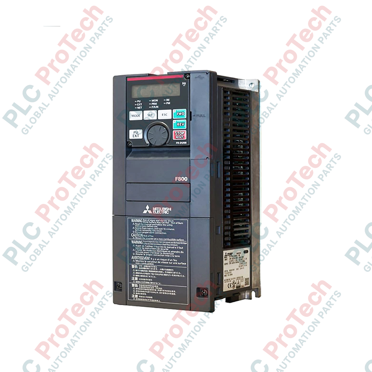
Description
Engineered specifically for heavy-duty fan and pump speed control, the Mitsubishi Electric FR-F840-00620-2-60 is a high-performance variable frequency drive belonging to the high-efficiency F800 Series. This unit operates on a three-phase 380V to 500V supply and is configured with standard control features optimized for energy-saving industrial applications. The FR-F840-00620-2-60 model includes a specialized protective circuit board coating to withstand demanding environmental conditions while omitting plated conductors. It features an integrated forced air-cooling system and complies with the IP21 environmental protective structure, making it ideal for clean, enclosed panel installations.
Key Features
-
Advanced Energy Saving: Built-in optimization algorithms reduce power consumption during variable torque applications.
-
Enhanced Environmental Resistance: Features protective conformal coating on internal printed circuit boards.
-
Flexible Input Support: Accommodates a wide input voltage fluctuation range of 323V to 550V AC.
-
Integrated Cooling: Equipped with active forced air cooling to maintain thermal stability under continuous operation.
-
IP21 Protection: Designed as an enclosed-type structure suitable for vertical panel mounting.
Applications
- Industrial ventilation systems and large-scale exhaust fans.
- Water supply, waste-water processing, and industrial pumping networks.
- Commercial HVAC air handling units and cooling towers.
- Boiler draft fans and secondary cooling loops in manufacturing plants.
Technical Specifications
| Manufacturer |
Mitsubishi Electric |
| Model Number |
FR-F840-00620-2-60 |
| Series |
F800 Series |
| Voltage Class |
400 V Class |
| Rated Input AC Voltage |
Three-phase 380 to 500 V, 50 Hz / 60 Hz |
| Permissible AC Voltage Fluctuation |
323 to 550 V, 50 Hz / 60 Hz |
| Permissible Frequency Fluctuation |
+/- 5% |
| Structure/Functionality |
Standard Model |
| Inverter Rated Current Code |
00620 |
| Control Specification Type |
-2 (CA Type) |
| Circuit Board Coating |
With Conformal Coating |
| Plated Conductor |
Without Plated Conductor |
| Protective Structure |
Enclosed Type (IP21 / IEC 60529) |
| Cooling System |
Forced Air Cooling |
| Net Weight |
15.0 kg |
| Shipping Weight (Calculated) |
17.0 kg |
Empirical Engineering Insights
Alternative Models & Compatibility
The "-2-60" suffix indicates that this model features coated internal boards and no plated conductors. It can directly replace standard Mitsubishi F800 units with matching current and voltage profiles in environments with elevated moisture or non-corrosive dust. If migrating from older F700 series models, check terminal space alignments as physical dimensions and parameter mappings have updated.
Application Pitfalls & Engineering Notes
Ensure the forced air-cooling fan intake and exhaust paths remain completely unobstructed. In heavy industrial enclosures, thermal dissipation is vital; the unit must be derated if operating in ambient temperatures continuously exceeding 40 degC inside tightly packed panels.
Commissioning & Wiring Tips
Always separate control circuit cables from main power cables to prevent electromagnetic coupling. Use shielded cables for analog inputs (terminal 2 and 4 references) and ensure the shield is grounded at the inverter-end ground plate only to eliminate ground loop noise.
Installation Guidelines
CRITICAL WARNING
Before beginning any installation, maintenance, or wiring procedures, isolate the primary input power supply. Wait at least 10 minutes after power-off to allow internal DC bus capacitors to discharge safely below 50V. Verify with a calibrated multimeter before touching internal terminals.
1
Mount the inverter vertically on a flat, non-flammable surface (such as a metal plate) to maximize heat dissipation from the rear heatsink.
2
Connect the physical protective earth (PE) ground to the designated ground terminal before wiring mains power lines to R/L1, S/L2, and T/L3.
3
Connect output motor cables strictly to terminals U, V, and W. Do not connect mains utility power to these output terminals, as doing so will permanently destroy the inverter.