Description
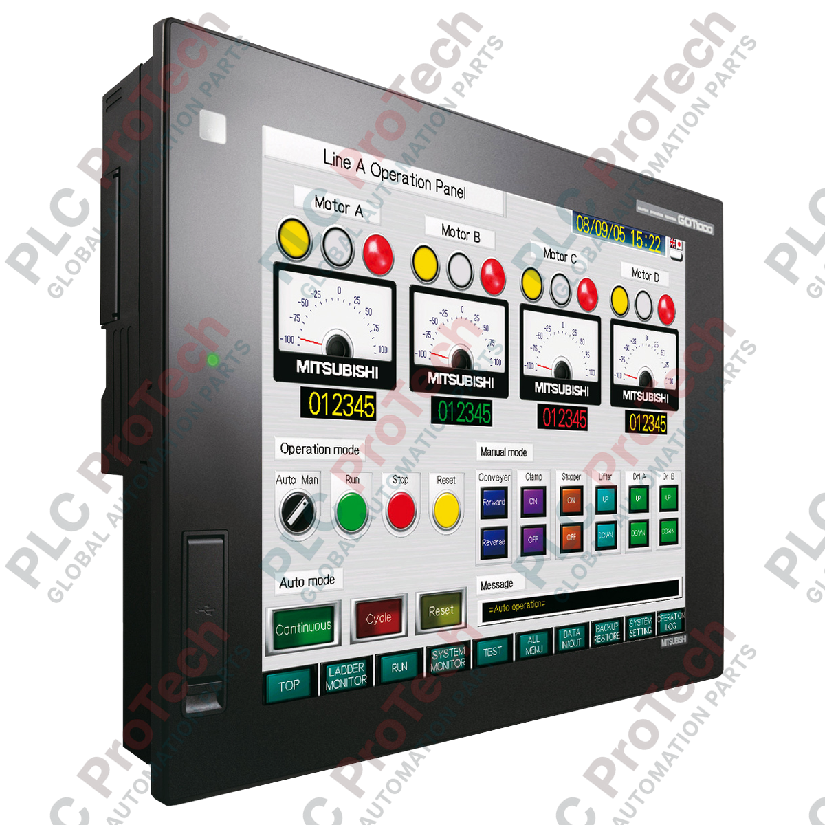
Optimizing operator interaction at the machine level, the Mitsubishi Electric GT1155-QSBD functions as a rugged, highly responsive human-machine interface (HMI) within the GOT1000 Series. Built with a 5.7-inch STN color display and supporting a 256-color palette, this terminal delivers clear process visualization and diagnostics for complex automated machinery. The unit is equipped with integrated serial communications and a high-speed USB port, allowing direct integration with programmable logic controllers (PLCs), variable frequency drives (VFDs), and other industrial automation devices.
Features
-
5.7-Inch STN Display: Provides a cost-effective, multi-color visualization panel with a resolution of 320 x 240 dots (QVGA).
-
Dual Serial Ports: Built-in RS-422/485 and RS-232 communication interfaces facilitate dual-channel device connectivity.
-
High-Speed Configuration: Rear-accessible USB Mini-B port enables rapid screen design transfers and system firmware updates.
-
Industrial Protection: IP67-rated front face ensures reliable operation in dusty, humid, or washdown-prone factory environments.
-
3 MB Flash Memory: Accommodates extensive user projects, alarm histories, logging data, and multi-language system fonts.
Applications
- Assembly and packaging machinery control panels
- Automotive shop floor visualization and local monitoring
- Water and wastewater local process pump stations
- Material handling systems and conveyor speed controls
Technical Specifications
| Parameter |
Specification Value |
| Manufacturer |
Mitsubishi Electric |
| Model Number |
GT1155-QSBD |
| Series |
GOT1000 (GT11 Series) |
| Display Size |
5.7 inches (Diagonal) |
| Display Type |
STN Color LCD (256 Colors) |
| Resolution |
320 x 240 pixels (QVGA) |
| Input Voltage |
24 VDC (+10% / -15%) |
| Power Consumption |
9.36 W or less |
| Built-in Memory |
3 MB Flash ROM |
| Front Panel Protection |
IP67 (when mounted with gasket) |
| Operating Temperature |
0 to 50 degC |
| Shipping Weight (Calculated) |
1.50 kg (excluding heavy freight packaging) |
| Dimensions (Calculated) |
167 x 135 x 60 mm |
Connections and Interfaces
| Port / Terminal |
Physical Type |
Function / Protocol |
| RS-422/485 |
D-Sub 9-pin (Female) |
Direct connection to Mitsubishi PLC (FX or Q series) |
| RS-232 |
D-Sub 9-pin (Male) |
Connection to PC, peripheral devices, or third-party controllers |
| USB |
Mini-B Port |
HMI configuration download/upload via GT Designer3 |
| Power Input |
Screw Terminal Block |
24 VDC input lines and functional grounding (FG) terminal |
Alternative Models & Compatibility
The GT1155-QSBD is part of the legacy GOT1000 portfolio. Direct modernization or migration is supported by the GOT2000 series, specifically the GT2105-QTBDS. When replacing a GT1155 unit, existing GT Designer2 or GT Designer3 projects (.g2 or .g3 formats) can be systematically converted to target the newer hardware profile without complete screen redesigns. Note that cabling pinouts for the serial ports remain highly compatible, but physical dimensional cutouts should be cross-checked during panel upgrades.
Application Pitfalls & Engineering Notes
Unlike high-end TFT active matrix modules, this STN display has a defined viewing angle. Avoid mounting the HMI in positions that require overhead or extreme side-angle reading. Furthermore, ensure that screens configured with static, high-contrast values do not remain active indefinitely; employ the screen-saver auto-off functions in the system settings of GT Designer to preserve backlighting lifespans and avoid pixel stagnation.
Commissioning & Wiring Tips
When routing the 24 VDC power supply lines, keep the HMI power run isolated from high-current AC motor leads or VFD cabling to prevent electrical noise coupling. The FG terminal on the power connector must be grounded using a dedicated ground line with a resistance of 100 ohms or less. If experiencing communications dropouts on RS-422 links over long distances, verify that a termination resistor is enabled at both end nodes of the serial chain.
Installation Guidelines
CRITICAL WARNING
Isolate and verify the de-energized state of all 24 VDC supply lines prior to beginning installation or wiring termination. Failure to isolate power can result in electronic destruction of the HMI communications transceiver chips and poses a safety risk to commissioning personnel.
1
Prepare a rectangular panel cutout matching the dynamic standard dimensions of 153 mm (W) x 121 mm (H).
2
Ensure the protective waterproof packing gasket is completely flat and clean of debris, then insert the HMI into the panel cutout.
3
Secure the terminal using the provided metal mounting fixtures. Tighten the screws to a nominal torque of 0.20 to 0.25 N-m to achieve a uniform IP67 seal without cracking the HMI bezel.
4
Connect the 24 VDC source and ground connections to the terminal block, then seat the communication cables onto their respective rear interfaces.