Description
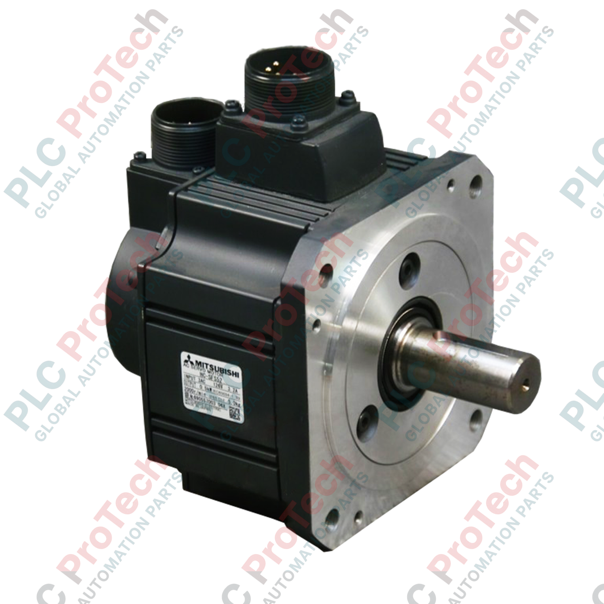
Engineered for high-demand closed-loop positioning systems, the Mitsubishi Electric HC-SFS352B AC Servo Motor delivers a robust 3.5 kW power output combined with medium inertia characteristics. Operating within the MELSERVO-J2-Super system architecture, this motor is specifically optimized for applications requiring stable speed regulation, high-resolution feedback, and precise deceleration performance. The integrated electromagnetic safety brake ensures structural holding power during power-loss scenarios, protecting critical mechanical axes from unexpected gravitational drops or inertia-driven overtravel.
Key Features
-
Medium Inertia Rotor: Provides ideal load-to-motor inertia matching for heavy-duty cyclical applications, preventing overshoot and mechanical resonance.
-
Integrated Electromagnetic Brake: 24VDC spring-activated holding brake designed to lock mechanical axes securely when de-energized.
-
High-Resolution Feedback: Equipped with a 17-bit incremental/absolute encoder providing 131,072 pulses per revolution for exceptional positioning resolution.
-
Rugged Environmental Protection: IP65 rated body enclosure (excluding shaft-through and connector areas) engineered to withstand harsh industrial workspaces.
Applications
- High-speed gantry systems and heavy material handling transfers.
- Multi-axis CNC machine tool feed axes and industrial machining tables.
- Continuous-operation textile machinery and commercial printing presses.
- Automated packaging machinery requiring strict dynamic synchronized motion.
Technical Specifications
| Parameter |
Value |
| Manufacturer |
Mitsubishi Electric |
| Model Identifier |
HC-SFS352B |
| Series |
MELSERVO HC-SFS Series |
| Rated Output |
3.5 kW |
| Rated Speed |
2000 r/min |
| Maximum Speed |
3000 r/min |
| Rated Torque |
16.7 N-m |
| Electromagnetic Brake |
Yes (Integrated, 24VDC holding type) |
| Brake Power Consumption |
30W at 20 degC |
| Compatible Voltage Class |
200 VAC |
| Encoder Specification |
17-bit Absolute/Incremental (131,072 p/rev) |
| Enclosure Protection Rating |
IP65 (excluding shaft opening) |
| Net Weight |
19.0 kg |
| Shipping Weight (Calculated) |
20.0 kg |
Connections and Interfaces
This servo motor features dedicated military-style MS round connectors for power and encoder connections, ensuring IP65 liquid resistance when mated correctly.
| Connector Type |
Terminal / Pin Reference |
Function Assignment |
| Power Plug |
U |
Motor Phase U |
| V |
Motor Phase V |
| W |
Motor Phase W |
| Earth |
Ground / PE Protective Earth |
| Brake Plug |
B1 |
Brake Terminal (Non-polarized) |
| B2 |
Brake Terminal (Non-polarized) |
Empirical Engineering Insights
Alternative Models & Compatibility
The HC-SFS352B belongs to the legacy MELSERVO-J2S line and pairs natively with the MR-J2S-350A or MR-J2S-350B amplifiers. For migrations or system updates to contemporary lines such as the MR-J4 series, you must transition to the HG-SR352B motor and MR-J4-350A/B amplifiers. Direct physical drop-in replacements with newer controllers require specific adapter cables due to differences in encoder feedback protocols.
Application Pitfalls & Engineering Notes
Continuous high-cycle operation near rated torque generates significant heat. Ensure the motor is bolted directly to an appropriate heat-sink flange (minimum recommended aluminum surface area is 400mm x 400mm x 20mm) to avoid thermal overload faults (AL.30 or AL.46) on the associated amplifier drive. Avoid placing the motor in non-ventilated enclosures without active external cooling.
Commissioning & Wiring Tips
To suppress electro-magnetic interference (EMI) that may trigger feedback faults (such as AL.16 or AL.20), route the motor power cables and the encoder cables in separate, grounded steel conduits. Keep the distance between these lines at least 10 cm apart. When commissioning the brake, ensure it is powered via an isolated external 24VDC power supply with an independent surge-suppression diode rather than a PLC output directly.
Installation Guidelines
CRITICAL WARNING:
Prior to starting mechanical or electrical installation, completely de-energize the servo amplifier and wait a minimum of 15 minutes for internal capacitor banks to fully discharge. Confirm zero voltage at the DC bus terminals before handling terminals or connectors.
1
Mount the motor securely to the machine base frame, verifying parallel alignment of the output shaft to prevent premature bearing wear.
2
Connect the physical system ground to the PE terminal of the motor housing, verifying resistance meets your local industrial safety standard (typically < 100 ohms).
3
Mate the military-style round plugs for power and encoder feedback, rotating the coupling ring completely until locked to maintain the IP65 seal.