Description
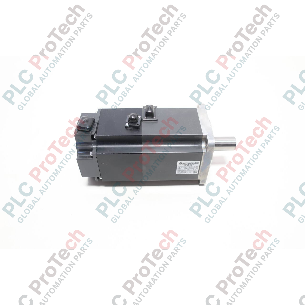
Designed for precise closed-loop motion control, the Mitsubishi Electric HF-KP73 industrial AC servo motor provides dynamic torque output in a compact footprint. Engineered specifically for pairing with the MELSERVO-J3 amplifier series, this low-inertia rotary motor delivers reliable positioning performance under high-duty cycling. Its high-resolution integrated encoder ensures micro-step precision, reducing tracking errors in demanding packaging, indexing, and positioning systems.
Key Features
- Low-inertia rotor design optimized for rapid acceleration and deceleration cycles.
- Integrated 18-bit absolute/incremental encoder providing 262,144 pulses per revolution for elite-level path accuracy.
- IP65-rated body construction offering protective resistance against dust and low-pressure water sprays.
- Standard straight shaft execution designed for rigid coupling or pulley integration.
- Optimized thermal dissipation winding design to maximize duty-cycle durations in enclosed industrial environments.
Typical Applications
- High-speed rotary indexing tables and dynamic pick-and-place systems.
- Packaging, labeling, and filling machinery requiring exact speed synchronization.
- Multi-axis Cartesian gantries and small XY positioning stages.
- Precision electronic component insertion machines.
Technical Specifications
| Parameter |
Specification |
| Manufacturer |
Mitsubishi Electric |
| Model Number |
HF-KP73 |
| Rated Output Power |
0.75 kW (750 W) |
| Rated Speed |
3000 r/min |
| Maximum Rotational Speed |
6000 r/min |
| Rated Torque |
2.4 N-m |
| Maximum Instantaneous Torque |
7.2 N-m |
| Rated Current |
5.2 A |
| Compatible Amplifier |
MR-J3-70A / MR-J3-70B / MR-J3-70T |
| Rotor Inertia |
1.13 x 10^-4 kg-m2 |
| IP Rating |
IP65 (excluding shaft passage) |
| Power Facility Capacity |
1.3 kVA |
| Operating Temperature |
0 to 40 degC |
| Country of Origin |
Japan |
| Shipping Weight (Calculated) |
3.2 kg |
| Package Dimensions (Calculated) |
240 mm x 160 mm x 140 mm |
Connections and Interfaces
| Terminal / Wire Color |
Power Pin Assignment |
Function / Description |
| Red |
U |
Motor Phase U Power Feed |
| White |
V |
Motor Phase V Power Feed |
| Black |
W |
Motor Phase W Power Feed |
| Green / Yellow |
PE |
Protective Earth Grounding |
Alternative Models & Compatibility
The HF-KP73 is backwards compatible as a mechanical replacement for older HC-KFS73 series motors; however, this transition requires matching drive updates, as the HF-KP utilizes the 18-bit serial encoder interface native to the MR-J3 amplifier series. If swapping hardware, make sure to adjust the motor ID parameters in your MR Configurator software settings before applying full operational load.
Application Pitfalls & Engineering Notes
-
Inertia Ratios: Keep the load-to-motor inertia ratio below 15:1. Exceeding this dynamic threshold can trigger system resonance, leading to unstable position loops and motor overheating.
-
Thermal Considerations: In closed cabinet setups, verify that ambient convective temperatures surrounding the motor housing do not exceed 40 degC to avoid winding insulation degradation.
-
Shaft Loading: Ensure radial loads do not exceed 392 N and axial loads remain below 147 N during operation to protect internal bearing geometries from premature wear.
Commissioning & Wiring Tips
To minimize high-frequency electromagnetic interference (EMI) from the drive's PWM outputs, run the motor encoder and main power cables in separate, grounded steel conduits separated by at least 10 cm. For high-vibration machinery mounts, implement flexible braided strain-relief loops on the connector pig-tails to avoid stress fractures on the internal connector soldered contacts.
Installation Guidelines
CRITICAL WARNING: ELECTRICAL SHOCK HAZARD
Isolate and lockout all incoming main supply voltage sources feeding the companion servo amplifier before carrying out any mounting or cable termination tasks. Wait at least 10 minutes to allow the amplifier dc-bus capacitors to fully discharge to safe voltage levels (< 50 VDC) before touching any motor wiring connections.
1
Mount the motor securely to a structural metal frame plate that acts as an integrated heatsink (minimum size: 250mm x 250mm x 6mm aluminum).
2
Align the motor shaft and driven load shaft accurately using a dial gauge to prevent angular offset wear on the bearings.
3
Connect the encoder cable housing ground terminal securely to the motor frame, and loop power lines through local ferrite cores to damp EMI propagation.