Description
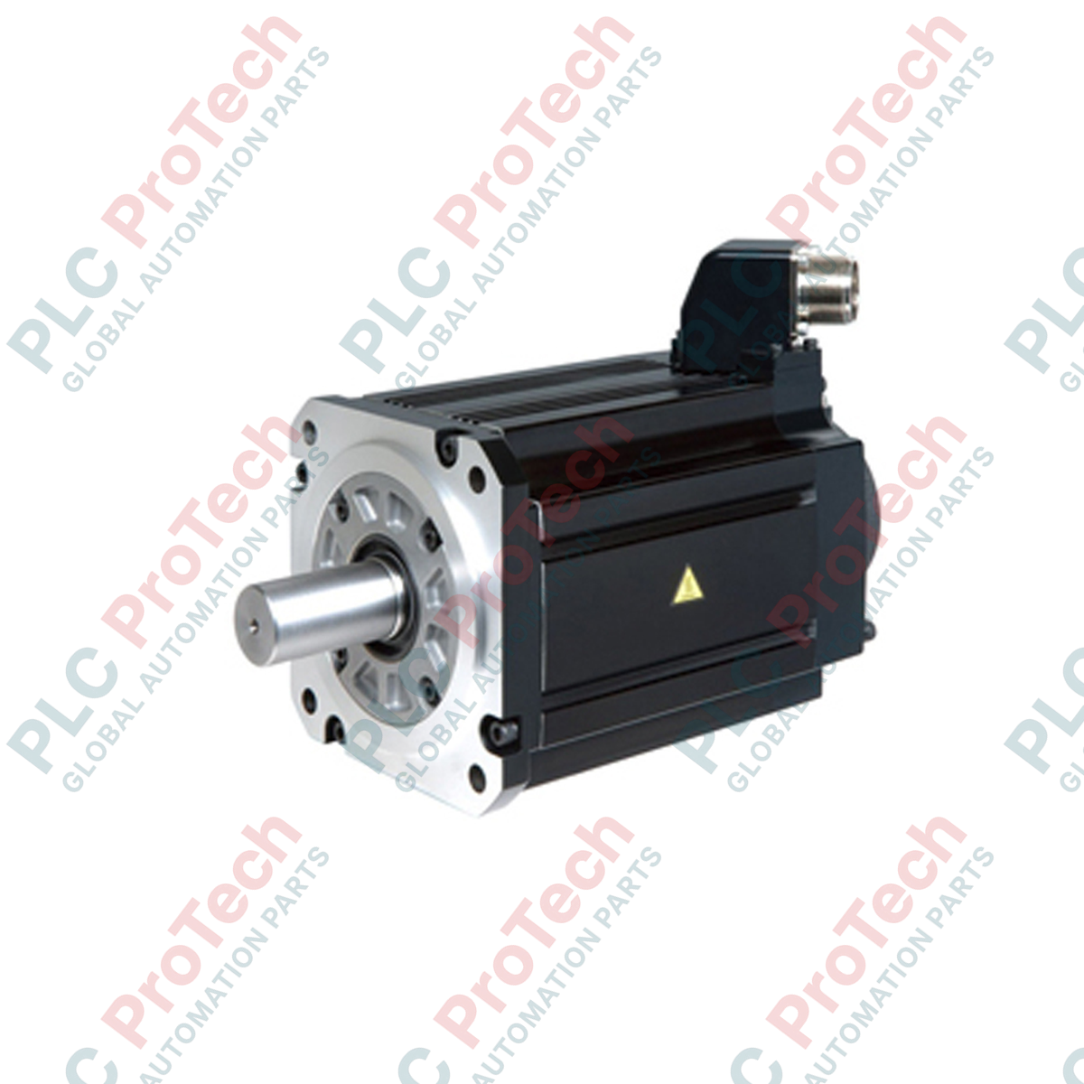
Engineered for demanding industrial motion control, the Mitsubishi Electric HG-JR703 AC servo motor delivers high-inertia performance within the MELSERVO-J4 drive ecosystem. This industrial-grade rotary motor is optimized for applications requiring stable torque output and high-capacity load management. Equipped with a high-resolution 22-bit absolute encoder, it provides precise positioning accuracy and feedback reliability, even under severe operating conditions. The robust IP67-rated construction ensures longevity in environments prone to dust, moisture, and non-corrosive oil splashes, making it a standard choice for heavy-duty manufacturing and automation systems.
Key Features
-
High-Inertia Design: Provides superior control stability for high-load systems with fluctuating inertia ratios.
-
High-Resolution Feedback: Integrated 22-bit absolute encoder (4,194,304 pulses/revolution) for exceptional position accuracy and velocity smoothness.
-
Environmental Protection: Class IP67 ingress rating (excluding the shaft pass-through) permits reliable operation in wet or dusty processing environments.
-
Optimized Compatibility: Fully matched with Mitsubishi MELSERVO-J4 series servo amplifiers (7.0 kW ratings) for rapid commissioning and tuning.
Applications
- Large-scale material handling systems and heavy transfer gantries
- High-speed industrial printing presses and paper converting machinery
- Automated press feed systems and heavy metal forming lines
- Multi-axis gantry robots and heavy-duty positioning tables
Technical Specifications
| Parameter |
Value |
| Manufacturer |
Mitsubishi Electric |
| Model Number |
HG-JR703 |
| Series Name |
HG-JR Series (MELSERVO-J4) |
| Rated Output Power |
7.0 kW |
| Rated Speed |
1500 r/min |
| Maximum Speed |
3000 r/min |
| Rated Torque |
44.6 Nm |
| Encoder Type |
22-bit Absolute Encoder |
| IP Protection Rating |
IP67 (excluding shaft) |
| Ambient Operating Temperature |
0 to 40 degC |
| Country of Origin |
Japan |
| Shipping Weight (Calculated) |
29.0 kg |
Empirical Engineering Insights
Alternative Models & Compatibility
The HG-JR703 acts as the direct technical successor to legacy HC-SFS702 series motors. When migrating from legacy series, parameters within the MR-J4 servo amplifier must be reconfigured to match the 22-bit absolute resolution profile. Ensure that the associated power and encoder cables are upgraded to match the modern dual-lock connector design, as pinouts differ from legacy screw-clamp terminals.
Application Pitfalls & Engineering Notes
Due to the 7.0 kW power class and high-inertia design, the regenerative energy generated during deceleration cycles can be substantial. When designing the control panel, standard internal drive regeneration capacity is frequently exceeded during rapid deceleration cycles. Install an external, properly rated regenerative option resistor (such as the MR-RB137-4) to prevent overvoltage trips (AL.30/AL.33) on the driver. Ensure that there is adequate ventilation around the non-drive end to prevent thermal trip faulting in high duty-cycle operations.
Commissioning & Wiring Tips
High-resolution encoders are sensitive to electromagnetic interference (EMI). Run the power and encoder cables in separate conduits with a minimum clearance of 30 cm. Verify that the motor frame is grounded directly to the main system PE panel bus using a low-impedance ground strap. For absolute position operation, set parameter PA03 in the MR-J4 amplifier before initiating the homing sequence.
Installation Guidelines
CRITICAL WARNING: HIGH VOLTAGE & RESIDUAL CHARGE RISK
Before performing any wiring or mechanical coupling on the motor, de-energize the main circuit breaker of the servo amplifier. Wait at least 15 minutes for the internal bus capacitors to discharge fully. Verify that the charge lamp on the front of the amplifier is completely off before touching terminals.
1
Mechanical Alignment: Mount the motor onto a rigid, flat surface. Ensure accurate alignment with the driven shaft using a flexible coupling to prevent radial and axial forces from exceeding the specified bearing limits.
2
Cable Routing & Strain Relief: Connect the power cable (U, V, W, PE) and the encoder cable, ensuring that there is no tension or sharp bending angles. Securely latch the IP67 connectors to preserve environmental sealing.
3
Initial Jog Test: Perform an initial test run in JOG mode without mechanical load coupling to verify correct rotation direction and feedback continuity before executing full automatic cycles.