Description
Handling high-inertia loads and precise speed regulation, the Mitsubishi Electric MR-J3-700A4 is a 400V class industrial servo drive engineered for demanding motion control architectures. This unit integrates seamlessly into the MELSERVO-J3 system landscape, utilizing advanced digital control loops to provide accurate torque, velocity, and position regulation when paired with high-capacity rotary servo motors. Designed with an analog and pulse train interface, it allows direct integration with standard PLC positioning modules and external motion controllers.
Features
-
Adaptive Auto-Tuning: Real-time estimation of load inertia ratio ensures rapid gain optimization and stable loop performance under varying load profiles.
-
Vibration Suppression: Advanced dual-frequency suppression filters counter mechanical resonance and protect mechanical transmission elements from high-frequency wear.
-
High-Resolution Feedback Compatibility: Direct interface for absolute or incremental high-resolution encoders, providing excellent positioning accuracy.
-
Integrated Protection Circuits: Overcurrent, regenerative overvoltage, overload, and encoder fault detection systems safeguard both driver and motor from electrical damage.
Applications
- Large-scale gantry robots and heavy-duty material handling axes.
- Multi-axis CNC machining centers, precision indexing tables, and metal forming machinery.
- Continuous web tension control in paper converting, printing, and high-speed packaging lines.
Technical Specifications
| Specification Parameter |
Value / Detail |
| Manufacturer |
Mitsubishi Electric |
| Model Number |
MR-J3-700A4 |
| Output Capacity |
7.0 kW |
| Rated Output Voltage |
3-phase 323 VAC |
| Rated Output Current |
17.0 A |
| Main Circuit Supply Voltage |
3-phase 380 to 480 VAC, 50/60Hz |
| Main Circuit Rated Current |
14.4 A |
| Permissible Voltage Fluctuation |
3-phase 323 to 528 VAC |
| Control Circuit Supply Voltage |
1-phase 380 to 480 VAC, 50/60Hz |
| Control Circuit Rated Current |
0.2 A |
| Power Consumption |
45 W |
| Cooling Mechanism |
Force-cooling (integrated fan) |
| Dynamic Brake |
Built-in |
| Net Weight |
6.2 kg |
| Shipping Weight (Calculated) |
8.0 kg |
| Country of Origin |
Japan |
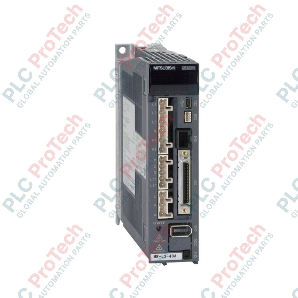
Power and Terminal Assignments
| Terminal Designation |
Function / Connection Assignment |
| L1 / L2 / L3 |
Main circuit AC power input (3-phase 380V to 480VAC) |
| L11 / L21 |
Control circuit AC power input (1-phase 380V to 480VAC) |
| U / V / W |
Servo motor power output connections |
| P+ / C / D |
Regenerative brake resistor configuration terminals |
| PE |
Protective Earth ground connections |
Empirical Engineering Insights
Alternative Models & Compatibility
The MR-J3-700A4 represents the analog/pulse train interface option. When migrating systems or selecting replacement spares, note that the MR-J3-700B4 utilizes the SSCNET III optical fiber bus and is not a direct electrical drop-in. For retrofits where MR-J3 models are reaching end-of-life, the MR-J4 series can serve as an alternative, but requires a conversion cable kit and parameter translation using MR Configurator2 software.
Application Pitfalls & Engineering Notes
Under continuous high-cycle operations with large-inertia loads, thermal saturation of the built-in dynamic brake resistor is a common failure vector. If the amplifier experiences frequent AL.30 (Regenerative Error) or AL.45 (Main Circuit Overheat) faults, confirm that the duty cycle matches the thermal specifications or install an external, high-capacity regenerative brake resistor between terminals P+ and C (ensuring the jumper between PR and C is removed).
Commissioning & Wiring Tips
Always route control I/O (CN1) cables separately from the main motor power cables (U/V/W) to prevent electromagnetic interference. Keep the encoder cable shield terminated securely at the drive chassis clamp. When using open-collector pulse inputs rather than differential line drivers on CN1, maximum feed frequency is significantly reduced, which can limit the top velocity performance of high-resolution profiles.
Installation Guidelines
CRITICAL SAFETY WARNING
Isolate and verify all power sources are completely de-energized before mounting, terminating, or servicing the unit. High voltage remains stored in the internal DC bus capacitors even after powering off. Wait at least 20 minutes and verify that the charge LED on the front face of the amplifier is completely extinguished before making contact with terminal connections.
1
Vertical Orientation: Mount the servo amplifier vertically on a flat, non-flammable mounting panel inside a sealed control enclosure. Ensure a minimum clearance of 40mm above and below the housing, and at least 10mm on both sides, to ensure unobstructed forced airflow through the cooling channels.
2
Ground Connection: Ground the drive's Protective Earth (PE) terminal to the cabinet's main copper bus bar using low-impedance copper wire of adequate gauge. Do not daisy-chain ground terminals between adjacent amplifiers.
3
Cable Termination: Ensure all power terminals are torqued to the manufacturer’s specifications. Loose connections will cause localized heating and terminal board degradation under continuous rated operational currents.