Description
Executing complex multi-axis synchronization within the MELSEC Q Series automation platform, the Mitsubishi Electric Q173DSCPU acts as a dedicated high-performance motion controller capable of managing high-speed, synchronized machine architectures. This controller operates side-by-side with standard Q Series PLC CPUs on a common base unit, leveraging the high-speed system bus to process sequences and motion paths in parallel. It utilizes the highly reliable SSCNET III/H optical fiber network to coordinate up to 32 axes of motion with microsecond-level precision, minimizing signal noise and latency across distributed servo drives.
Features
-
Multi-Axis Control Capacity: Manages up to 32 independent or fully synchronized motion axes via a single CPU slot.
-
Advanced Compensation Functions: Supports built-in backlash compensation, electronic gear configuration, and phase compensation under the SV22 operating system environment.
-
Manual Override Operations: Features a built-in JOG operation function to simplify commissioning, manual axis alignment, and physical boundary testing.
-
Parallel Processing Architecture: Integrates onto the MELSEC Q series base unit to execute motion profiles independently of the main sequence program cycle.
-
SSCNET III/H Protocol: Offers deterministic, noise-immune high-speed serial communication via fiber-optic cables, optimizing data exchange with MR-J4/MR-J3 servo amplifiers.
Applications
- High-speed pick-and-place packaging systems requiring rapid electronic gearing.
- Multi-station rotary indexing tables with precise mechanical backlash compensation.
- Synchronized printing presses, web tension control systems, and industrial winding machines.
- Precision semiconductor packaging and material handling gantry robots.
Technical Specifications
| Specification Parameter |
Value |
| Manufacturer |
Mitsubishi Electric |
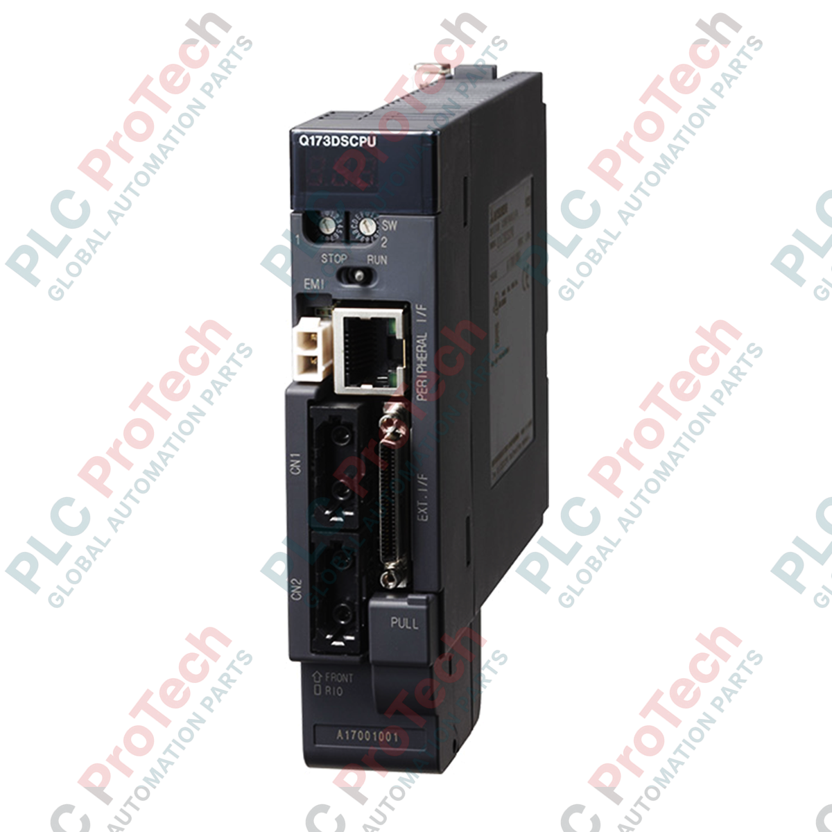
| Model Identifier |
Q173DSCPU |
| Series |
MELSEC Q Series |
| Control Axes Limit |
Up to 32 axes |
| Internal Current Consumption (5VDC) |
1.75 A |
| Communication Protocol |
SSCNET III/H (150 Mbps, full duplex) |
| Control Method |
PTP (Point-to-Point) Control, Interpolation Control, Synchronous Control |
| Programming Software |
MT Developer2 (within MELSOFT suite) |
| Physical Dimensions |
120.5 mm x 27.4 mm x 120.3 mm |
| Net Weight |
0.33 kg |
| Shipping Weight |
3.00 kg |
| Country of Origin |
Japan |
Empirical Engineering Insights
Alternative Models & Compatibility
The Q173DSCPU represents a direct generational upgrade over the older Q173HCPU. When migrating older systems to this CPU, ensure that your existing MR-J3 servo amplifiers are either configured for SSCNET III/H compatibility mode or upgraded to MR-J4 models. Note that the program structure under MT Developer2 differs slightly from the legacy MT Developer format; mechanical system programs must be converted to the newer Motion SFC (Sequential Function Chart) structure to run correctly on this controller hardware.
Application Pitfalls & Engineering Notes
When utilizing all 32 axes under complex electronic cam or phase compensation structures (SV22), pay close attention to the operation cycle settings in MT Developer2. If the operation cycle is set too low (e.g., 0.222 ms) and CPU processing exceeds 100%, watchdog timer errors or synchronous communication dropouts will occur. For heavy multi-axis coordination, consider balancing processing load by extending the operation cycle to 0.444 ms or 0.888 ms.
Commissioning & Wiring Tips
SSCNET III/H uses specialized plastic optical fiber (POF) cables. Ensure the minimum bending radius of these optical cables is never compressed below 25 mm. Sharp bends or over-tightened cable zip-ties will cause signal degradation, resulting in intermittent SSCNET loop initialization failure and AL.37 (Parameter Error) or AL.3c (Communication Error) faults on connected MR-J4 servo drives. Keep the protective optical caps on all unused ports to prevent dust contamination.
Installation Guidelines
CRITICAL WARNING: Completely isolate and de-energize the main incoming three-phase power supply and the PLC base unit power supply before mounting or inserting the Q173DSCPU module. Failure to de-energize the backplane prior to installation risks permanent ESD or arc-flash damage to the internal ASIC bus interface of both the base unit and the motion controller.
1
Align the lower hook of the Q173DSCPU module into the module fixing hole located on the MELSEC Q series base unit.
2
Push the top of the module firmly against the backplane connector until it locks flat with the base unit, and tighten the top module mounting screw to 0.36-0.48 N·m.
3
Connect the Q170BAT battery module to the internal battery connector behind the front cover flap to preserve internal retentive memory parameters.
4
Remove the protective dust plugs from the SSCNET III/H optical ports and insert the fiber optic connectors from the master loop until an audible click is felt.