Description
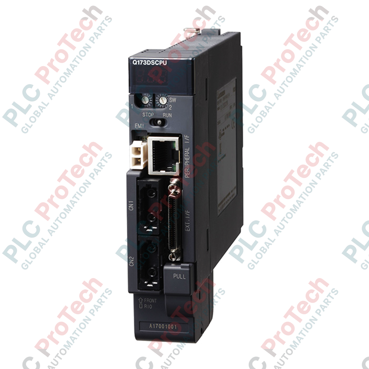
Optimizing synchronization across multiple axes in complex machinery, the Mitsubishi Electric Q173HCPU coordinates up to 32 independent servo axes within a single system. This high-density motion CPU module integrates directly onto the standard MELSEC Q Series multi-CPU backplane, sharing high-speed data transmission buses with host PLC modules to minimize processing overhead. Utilizing the noise-resistant, high-speed fiber-optic SSCNET III network, it provides reliable closed-loop control over servo drives and motors, preventing communication latency even in high-electromagnetic-noise environments. Designed to slot in directly to the right of the primary PLC CPU, the controller utilizes a clear base cover for status visualization and is structurally built to withstand heavy vibrational environments when panel-mounted.
Features
-
32-Axis Control Capability: Manages up to 32 physical axes of servo amplifiers via high-speed optical fiber linkages.
-
Multi-CPU Architecture Support: Configurable alongside up to three additional Q Series CPUs for decentralized load distribution between control logic and motion trajectories.
-
SSCNET III Integration: Dual high-speed optical ports provide reliable, noise-immune communications over fiber-optic cabling.
-
Vibration-Resistant Design: Accommodates panel installation with unit-fixing screws to ensure connection integrity in high-vibration applications.
-
Clear Cover Interface: Transparent protective housing permits immediate inspection of diagnostic status indicators and interface ports.
Applications
- High-speed pick-and-place electronic assembly systems.
- Synchronized web-handling, packaging, and printing systems.
- Multi-axis gantry robots and industrial Cartesian systems.
- Complex automated sorting and bottling lines requiring precise timing.
Technical Specifications
| Parameter |
Value / Specification |
| Manufacturer |
Mitsubishi Electric |
| Model Code |
Q173HCPU |
| Series |
MELSEC Q Series |
| Control Axes |
Up to 32 axes |
| Communication Protocol |
SSCNET III (Fiber-Optic Network) |
| Mounting Compatibility |
DIN Rail (with adapter) or Panel Direct Mounting (recommended for high-vibration) |
| Multi-CPU Placement |
CPU slot No. 2 or later (always to the right of PLC CPU) |
| Empty CPU Slot Setting |
Not allowed between active CPU modules |
| Operating Temperature Range |
0 to 55 degC |
| Storage Temperature Range |
-25 to 75 degC |
| Shipping Weight (Calculated) |
3.0 kg |
| Package Dimensions (Calculated) |
250 mm x 180 mm x 110 mm |
Connections and Interfaces
| Connector / Terminal |
Interface Type |
Functional Assignment |
| CN1 Connector |
Optical Transceiver |
SSCNET III communication loop for Axes 1 to 16 |
| CN2 Connector |
Optical Transceiver |
SSCNET III communication loop for Axes 17 to 32 |
| EMI Terminal |
Discrete I/O Connection |
Forced stop (External Interlock) input terminal |
| P1/P2/P3 Ports |
Serial / Encoder Port |
Manual Pulse Generator / External synchronous encoder inputs |
Empirical Engineering Insights
Alternative Models & Compatibility
When replacing an older Q173CPUN module, be aware that the Q173HCPU transitions from the copper-based SSCNET to the fiber-optic SSCNET III system. You must upgrade all associated cabling to optical fiber (MR-J3BUS or compatible) and ensure that the connected servo drives (e.g., MR-J3-B or MR-J4-B series in J3-compatibility mode) are fully compatible with SSCNET III protocols. Furthermore, check the Operating System software (SV13/SV22) programmed within the module; mismatching OS versions with the host GX Works2 / MT Developer2 configurations will trigger a CPU verification fault upon system boot.
Application Pitfalls & Engineering Notes
A common issue during multi-CPU configuration is allocating empty slots. The Q173HCPU cannot be separated from the host PLC CPU (CPU No.1) by an empty slot on the base unit. In addition, dust or microscopic scratches on the optical fiber connectors (CN1/CN2) are the primary causes of transient communication drops (alarm code AL.37). Always ensure the protective rubber caps remain fitted to unused optical ports and clean fiber ends with designated optical cleaning swabs prior to insertion.
Commissioning & Wiring Tips
When routing the fiber-optic cables, enforce a minimum bending radius of 25 mm. Exceeding this limit causes signal attenuation, leading to intermittent link losses. During software commissioning in MT Developer2, ensure that the multi-CPU shared memory configurations align exactly between the PLC program and the Motion SFC code to prevent parameter overlap errors.
Installation Guidelines
CRITICAL WARNING: HIGH VOLTAGE & ESD HAZARD
Isolate all external power sources feeding the base unit and connected servo controllers before handling the module. Retained electrical charges in servo capacitors pose a lethal shock hazard. Wait a minimum of 10 minutes post-power-down before disconnecting cabling or extracting the module. Always wear a grounded wrist strap to prevent static discharge to exposed internal circuitry.
1
Verify that the main base unit power supply is turned off. Confirm that the module guide slots are free of dirt or particulate matter.
2
Engage the lower positioning projection of the Q173HCPU into the base unit's module fixing hole, keeping the module perpendicular to the backplane.
3
Push the top of the module firmly toward the backplane until the upper module lock clicks securely. If operating in high-vibration environments, secure the top of the module with mounting screws (tightening torque: 0.36 to 0.48 N-m).
4
Remove the protective covers from the CN1 and CN2 optical ports, and firmly connect the SSCNET III fiber-optic cables until they click into place. Keep the minimum bending radius at 25 mm or higher.