Description
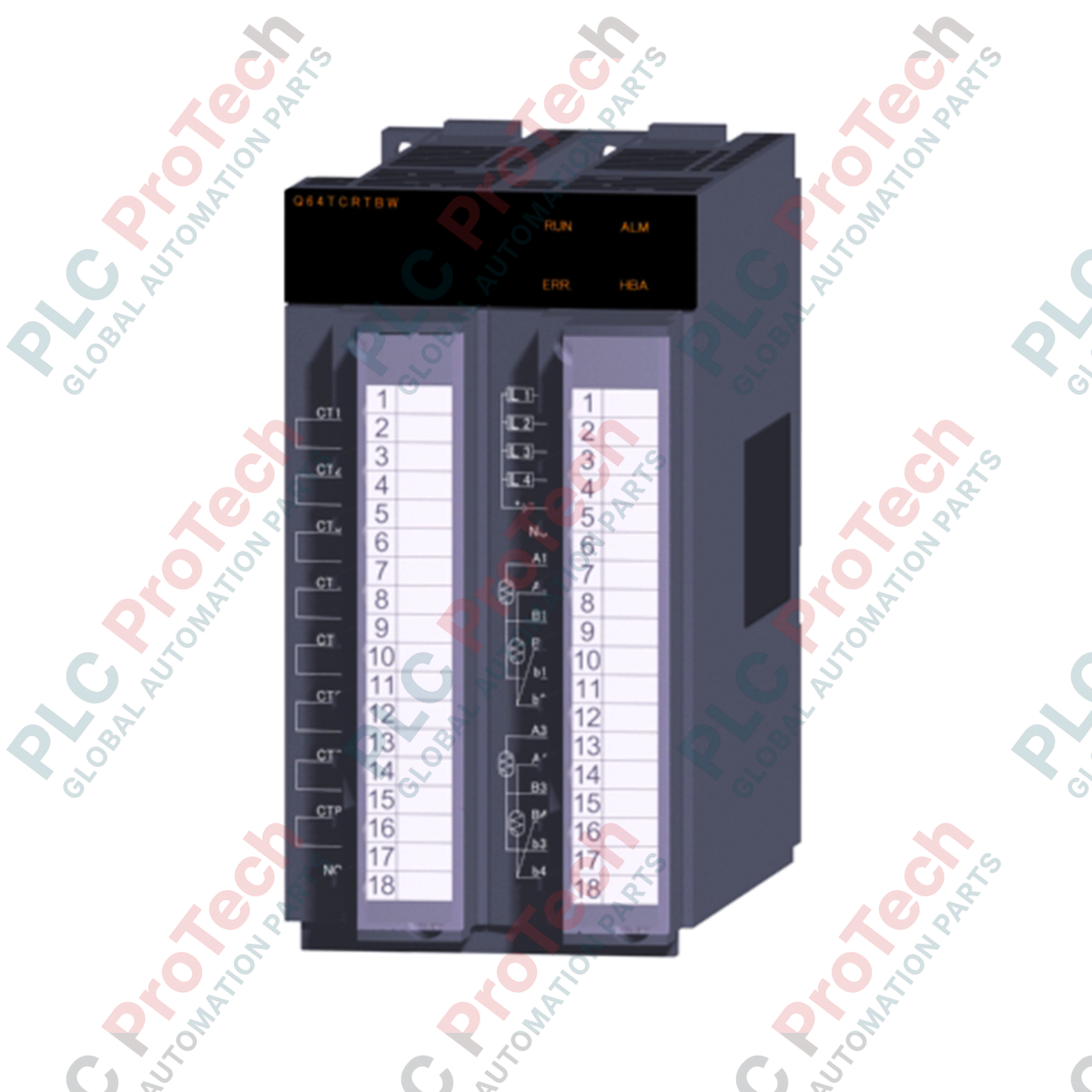
Integrating high-accuracy thermal loops directly into the MELSEC Q control architecture, the Mitsubishi Electric Q64TCRTBW temperature control module delivers hardware-based PID processing across four independent channels. This specialized module interfaces directly with Pt100 and JPt100 platinum resistance temperature detectors (RTDs), executing high-speed 500 ms sampling cycles to guarantee thermal stability in precision processes. By offloading PID calculations and heater monitoring from the host PLC CPU, the Q64TCRTBW ensures deterministic control and fast response times, outputting pulse signals via transistor outputs to drive external solid-state relays (SSRs).
Features
-
Four-Channel Control: Manages up to four independent temperature loops per module.
-
RTD Compatibility: Supports standard Pt100 and JPt100 resistance temperature detectors.
-
Heater Disconnection Detection: Supports real-time current monitoring using CTL-series external current sensors to detect element burnout.
-
Autotuning PID: Integrated tuning algorithms automatically calculate optimal proportional, integral, and derivative constants.
-
Transistor Outputs: Built-in transistor pulse outputs (10 to 30 VDC, 0.1 A per point) optimized for solid-state relay driving.
-
Galvanic Isolation: Complete transformer insulation between input channels and ground, and between individual channels to prevent cross-talk and common-mode noise.
Applications
- Semiconductor manufacturing wafer heating panels and oxidation furnaces.
- Plastic injection molding, extrusion barrels, and die temperature control.
- Food processing ovens, packaging sealing bars, and hot-melt systems.
- Environmental simulation chambers, laboratory incubators, and industrial autoclaves.
Technical Specifications
| Parameter |
Specification Value |
| Manufacturer |
Mitsubishi Electric |
| Model Number |
Q64TCRTBW |
| Control Input Channels |
4 channels |
| Sensor Input Type |
Pt100, JPt100 (3-wire RTD) |
| Sampling Cycle |
500 ms for all 4 channels |
| Control Output |
Transistor output (ON/OFF pulse) |
| Rated Load Voltage |
10 to 30 VDC |
| Maximum Load Current |
0.1 A per point, 0.4 A per common |
| Input Impedance |
1 M-Ohm |
| Accuracy (at 25 +/- 5 degC) |
Full scale x (+/- 0.3%) |
| Accuracy (0 to 55 degC) |
Full scale x (+/- 0.7%) |
| Isolation Method |
Transformer isolation between inputs and ground, and between input channels |
| Withstand Voltage |
500 VAC for 1 minute |
| I/O Slot Allocation |
32 points (16 free points + 16 intelligent points) |
| Internal Current Consumption (5 VDC) |
0.64 A |
| External Connections |
Two 18-point M3 screw terminal blocks |
| Dimensions (H x W x D) |
98 mm x 55.2 mm x 112 mm |
| Module Weight |
0.30 kg |
| Shipping Weight (Calculated) |
1.3 kg |
Empirical Engineering Insights
Alternative Models & Compatibility
The "BW" suffix indicates integrated heater disconnection detection capabilities. When replacing a standard Q64TCRT module with a Q64TCRTBW, confirm that the I/O allocation parameters in GX Works2 or GX Works3 are updated. Although it physically occupies only one slot on the MELSEC Q base unit, the system reserves 32 I/O points (the equivalent of two standard slots) to handle control variables and the additional current-sensor inputs.
Application Pitfalls & Engineering Notes
Executing auto-tuning on systems with extremely high thermal dynamics or rapid heat dissipation can lead to PID overshoot or loop calculation timeouts. In highly dynamic thermal processes, manually tuning the proportional band (P) from 0.0% (which defaults to 2-position/ON-OFF control) to a conservative initial value is recommended to prevent thermal stress on solid-state devices. Additionally, ensure the external current sensor (CTL-6-P, CTL-6-PH, or CTL-12-S36-8) is matched to the specific heater load to avoid false disconnection alarms.
Commissioning & Wiring Tips
Platinum RTDs (Pt100/JPt100) are highly vulnerable to induced electromagnetic noise. Always run 3-wire RTD cabling in dedicated instrument trays separate from high-voltage AC lines. Shielded cables must be grounded exclusively at a single point on the control cabinet ground bar to prevent ground loops. Note that any resistance mismatch among the three RTD wires will cause direct measurement drift; ensure all three connections are of identical length and wire gauge.
Installation Guidelines
CRITICAL SAFETY WARNING
Before attempting to mount, wire, or remove the module, ensure that all external power sources feeding the PLC rack and the heater circuits are completely de-energized. Failure to isolate power can result in electrical shock, hardware destruction, or unpredictable output behavior.
1
Hook the upper mounting tab of the module into the MELSEC Q base unit slot guide and press the module firmly down into the backplane connector. Tighten the module fixing screw to 0.36 to 0.48 N-m.
2
Perform wiring of the RTD inputs and transistor outputs onto the 18-point terminal block. Tighten the terminal block screws to a torque of 0.42 to 0.58 N-m using M3 crimp terminals.
3
Route CT sensor cables through the dedicated current sensor input terminals on the module if heater burnout monitoring is utilized.
4
Power up the PLC base unit, download the I/O configurations, and execute an initial autotune cycle to establish base PID control loops.