Description
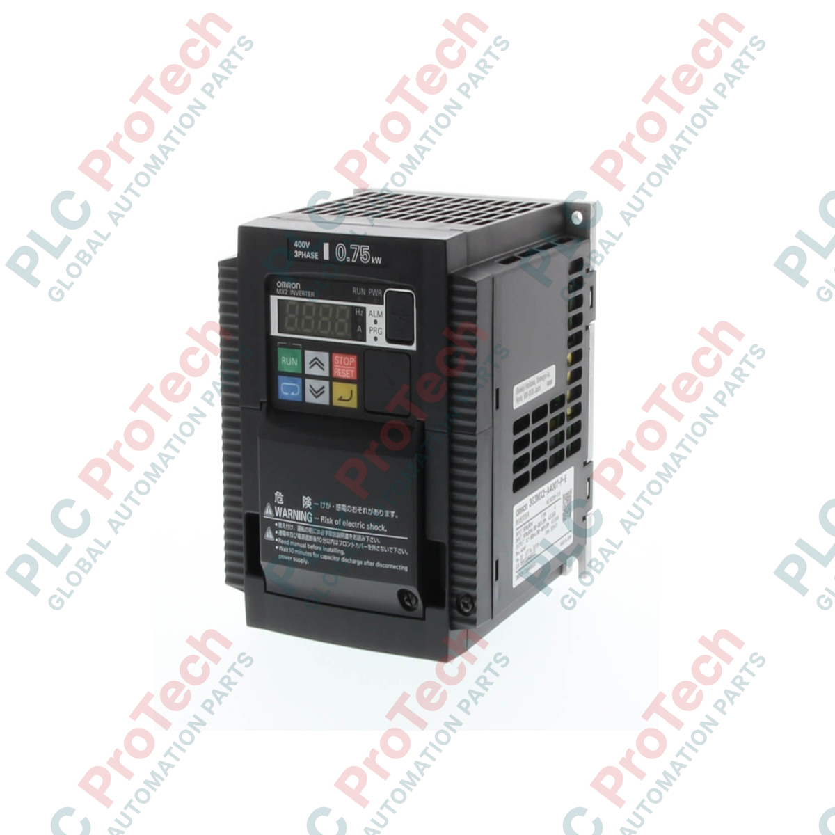
Engineered to deliver exceptional vector control and dynamic performance for industrial motors, the Omron 3G3MX2-A4004-ZV1 is a highly integrated, 3-phase 400 V AC variable frequency drive from the MX2 Series. With a rated capacity of 0.4 kW, this multi-function compact inverter is optimized for applications requiring high starting torque, accurate speed regulation, and functional safety integration directly within the drive control loop.
Features
-
Dual Rating Support: Optimized for heavy-duty applications requiring up to 200% starting torque at 0.5 Hz.
-
Integrated Functional Safety: Built-in dual safety inputs conform to ISO 13849-1 Cat 3 / PLd without requiring external contactors.
-
Permanent Magnet Motor Control: Compatible with both standard induction motors (IM) and permanent magnet synchronous motors (PM).
-
Modbus RTU Communication: Embedded RS-485 serial communication port supports seamless field integration.
-
Side-by-Side Mounting: Space-saving chassis design allows compact panel layout configurations.
Applications
- High-torque material handling conveyors and sorting lines.
- Industrial packaging systems with rapid start/stop cycles.
- Pumping and ventilation systems utilizing permanent magnet motor technology.
- Automated assembly systems requiring integrated safety functions.
Technical Specifications
| Parameter |
Value |
| Manufacturer |
Omron |
| Model Code |
3G3MX2-A4004-ZV1 |
| Series |
MX2 Series |
| Input Voltage Class |
3-phase 380 to 480 V AC (+10% / -15%), 50/60 Hz (+/- 5%) |
| Applicable Motor Capacity (CT) |
0.4 kW (Constant Torque) |
| Output Rated Current (CT) |
1.8 A |
| Enclosure Rating |
IP20 / Panel-mounting (IP10 min.) |
| Control Method |
Phase-controlled sinusoidal PWM (V/f or Open-loop vector) |
| Built-in Communication |
Modbus RTU (RS-485) |
| Safety Standards |
ISO 13849-1 Cat 3 / PLd, IEC 60204-1 Stop Category 0 |
| Operating Temperature Range |
-10 to +50 degC (no freezing) |
| Unit Weight |
1.6 kg |
| Shipping Weight (Calculated) |
4.0 kg |
Connections and Interfaces
| Terminal Symbol |
Functional Description |
| R/L1, S/L2, T/L3 |
Main power supply inputs (3-phase 400 V AC) |
| U/T1, V/T2, W/T3 |
Inverter output terminals connected to the AC motor |
| PD/+, P/+ |
External DC reactor terminal (remove jumper to install) |
| P/+, RB |
Braking resistor connection terminals |
| S1, S2, G |
Safety function terminals (STO - Safe Torque Off inputs) |
Empirical Engineering Insights
Alternative Models & Compatibility
The "-ZV1" suffix indicates a multi-function firmware revision optimized for expanded parameters and enhanced PM motor synchronization profiles. When replacing standard or older MX2 series non-ZV1 units, ensure to backup parameter sets using CX-Drive software, as certain memory maps may require scaling or verification during conversion.
Application Pitfalls & Engineering Notes
When operating in enclosed panels under sustained high-torque conditions, thermal load may trigger an E05 overload fault code. Side-by-side mounting is fully supported, but a derating of 10% in output current is recommended if ambient temperatures exceed 40 degC inside the enclosure. Always ensure the internal cooling fan duct remains free of debris.
Commissioning & Wiring Tips
For compliant safety loop deployment (STO), ensure the factory-installed shorting bar between S1, S2, and G is completely removed before connecting to your safety relay module or light curtain controller. If utilizing long motor cable runs exceeding 50 meters, an output AC dV/dT filter must be installed to prevent high voltage spikes from degrading the motor winding insulation.
Installation Guidelines
CRITICAL WARNING: HIGH VOLTAGE HAZARD
Isolate all primary AC power feeds before commencing mechanical installation or terminal wiring. Internal storage capacitors retain lethal charges. Wait a minimum of 10 minutes after disconnecting input power and verify that the charge indicator LED on the front panel is completely off before servicing terminal blocks.
1
Mount the inverter vertically on a flat, non-flammable surface inside a dust-free control cabinet using M4 mounting hardware.
2
Ensure minimum clearances are maintained: at least 10 cm above and below the drive housing to ensure unrestricted convection cooling.
3
Connect the protective earth terminal (Ground) to a low-impedance master grounding bar before wiring any primary input power terminals.
4
Wire the R/L1, S/L2, and T/L3 incoming power leads using shielded wire, terminating the shield grounding clamps correctly to mitigate electromagnetic interference (EMI).