Description
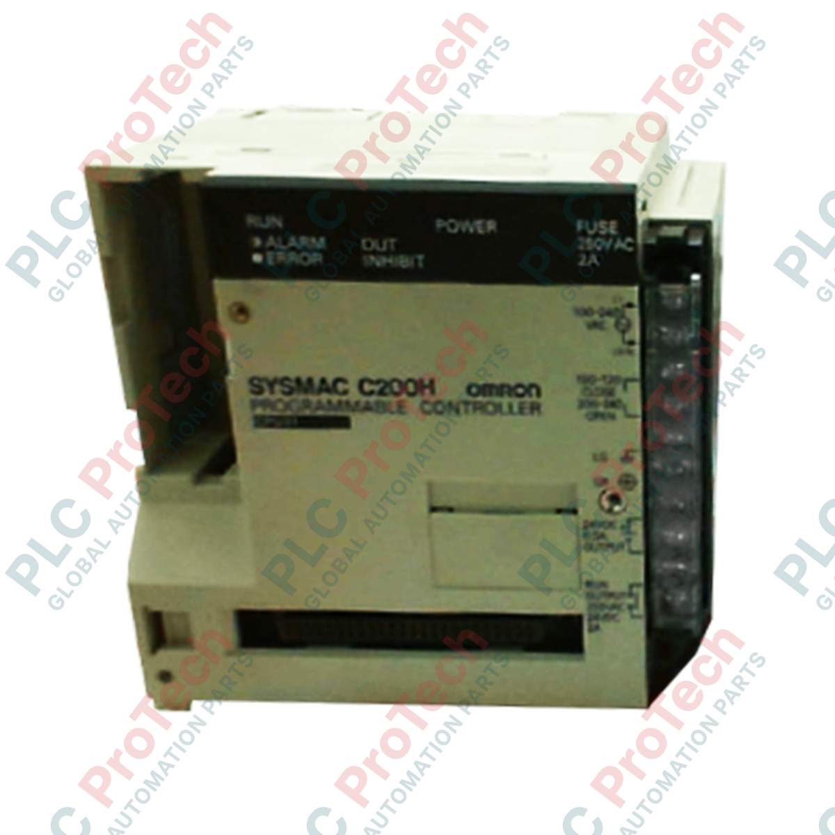
Managing complex logic control sequences within legacy system architectures, the Omron C200H-CPU21-E functions as a high-reliability central processing unit for the classic Omron C200H PLC platform. This module features flexible execution times and dual-voltage power configuration, making it well-suited for legacy migration and direct drop-in field replacements. By incorporating built-in control input and output terminals, the C200H-CPU21-E operates independently of dedicated I/O modules for primary startup and run status signaling, maintaining system uptime across older industrial installations.
Features
-
Dual-Voltage Selector: Supports selectable power inputs of 100 to 120 VAC or 200 to 240 VAC.
-
Direct Control Interfaces: Dedicated START input (24 VDC, 10 mA) and RUN dry contact output (2 A maximum capacity).
-
Flexible Refreshing Methods: Programmed, cyclic, scheduled, and zero-cross I/O refreshing modes.
-
Memory Cassette Support: Holds up to 6,974 words of application logic and data register memory.
-
Battery-Backed Protection: Preserves HR bits, AR bits, CNT values, and DM data areas during input power failures.
-
Advanced Self-Diagnostics: Monitors CPU failures, battery levels, scan time limits, memory errors, I/O bus verification, and specialized expansion modules.
Applications
- Legacy factory automation and modernization schemes.
- Material handling conveyor lines and sorting systems.
- Automated packaging machinery and cartoning lines.
- Water treatment pumping control panels and environmental monitoring.
Technical Specifications
| Specification Parameter |
Technical Rating / Value |
| Manufacturer |
Omron |
| Model Reference |
C200H-CPU21-E |
| Product Series |
C200H Series |
| Power Supply Voltage |
100 to 120 VAC / 200 to 240 VAC (selectable) |
| Basic Instruction Execution Time |
0.75 to 2.25 microseconds |
| Function Instruction Execution Time |
34 to 724 microseconds |
| Memory Capacity |
6,974 words (with 8K-word memory cassette) |
| START Input Signal |
24 VDC, 10 mA (controls execution state) |
| RUN Output Contacts |
Dry contact, Max 2 A 250 VAC (resistive), 0.5 A 250 VAC (inductive), 2 A 24 VDC |
| Standard Battery Lifespan |
4 years at 25 degC ambient temperature |
| Compliance Certifications |
UL Listed (File E95399), CSA Certified (File LR51460) |
| Country of Origin |
Japan |
| Shipping Weight (Calculated) |
2.0 kg |
| Package Dimensions (Calculated) |
260 x 160 x 140 mm |
Connections and Interfaces
| Terminal Identifier |
Functional / Circuit Assignment |
| START IN (+) / (-) |
24 VDC input logic to force RUN/STOP state externally. |
| RUN OUT (Dry Contacts) |
Internal relay contact closes when CPU completes successful initialization. |
| AC (L1) / (L2) |
Power input connection point (100-120 VAC or 200-240 VAC). |
| GR / LG |
System ground and line ground shield paths to prevent electrical noise. |
Empirical Engineering Insights
Alternative Models & Compatibility
The C200H-CPU21-E offers extended physical I/O control options over the baseline C200H-CPU01-E, which lacks dedicated START and RUN terminals. When upgrading an existing control panel to newer Omron platforms (such as the CS1D series), logic translation is required as memory mapping structures and physical backplanes do not feature backward physical compatibility.
Application Pitfalls & Engineering Notes
Never insert or remove memory cassettes (RAM or EEPROM packs) while the backplane has active power applied. This practice risks damaging internal CMOS components and corrupting stored application firmware. Additionally, if the ambient operating temperature in the enclosure consistently exceeds 40 degC, expect the internal backup battery runtime to degrade significantly below its rated 4-year standard.
Commissioning & Wiring Tips
To protect the internal RUN output contacts from back-EMF voltage surges, always install an external surge-suppressor (RC snubber for AC, flyback diode for DC) across inductive loads such as solenoid coils or contactor coils wired to this contact interface.
Installation Guidelines
CRITICAL WARNING: Disconnect and isolate all primary power supplies before attempting to mount, wire, or adjust the CPU module. Verify that the voltage configuration jumper matches your local utility power (110 VAC vs 220 VAC) to avoid catastrophic component destruction.
1
Align the top hook of the C200H-CPU21-E onto the dedicated slot of the C200H base unit rack, then rotate the unit downward until the bottom latch snaps firmly into place.
2
Tighten the upper and lower mounting screws to 0.8 N-m torque settings to prevent vibrations from loosening the backplane bus connection.
3
Verify that the ground terminal is securely connected to a low-impedance earth ground to safeguard diagnostic components against high-frequency line interference.