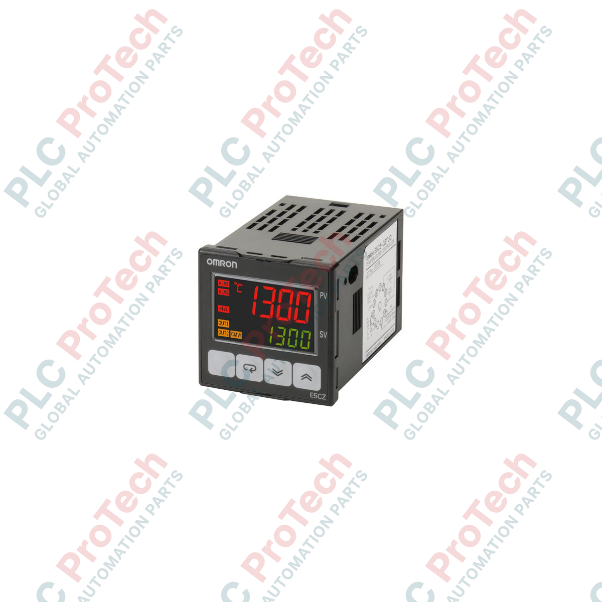
Description
For critical thermal regulation loops, the Omron E5CZ-Q2MT AC100-240 process controller provides high-accuracy PID control within a standard 1/16 DIN footprint. Built with a highly responsive 150 ms sampling period, this multi-input unit supports a wide array of temperature sensors and analog inputs, delivering stable control outputs for demanding industrial thermal processes. Equipped with a 12 VDC voltage output, it is engineered specifically to cycle external solid-state relays (SSRs) with minimal switching latency, while its dual auxiliary outputs allow for independent alarm configuration and system protection loops.
Features
-
Universal Input Flexibility: Supports diverse inputs including Thermocouples, Platinum Resistance Thermometers (Pt100/JPt100), and analog voltage/current signals.
-
High-Speed Processing: 150 ms sampling loop updates control calculations continuously to handle fast thermal response systems.
-
SSR Control Output: Generates a robust 12 VDC voltage output to drive high-performance solid-state relays.
-
Dual Alarm Relays: Two independent auxiliary SPST-NO relay outputs for comprehensive high/low limit and deviation monitoring.
-
Clear Dual Display: 11-segment PV/SV characters provide high-contrast visualization of active process states and target setpoints.
Applications
- Industrial packaging machinery sealing bars and hot-melt adhesive units
- Plastic extrusion lines and injection molding machine barrel zones
- Food processing ovens, sterilizers, and pasteurization systems
- Environmental simulation chambers and laboratory incubation systems
Technical Specifications
| Specification Parameter |
Technical Value |
| Power Supply Voltage |
100 to 240 VAC, 50/60 Hz |
| Operating Voltage Range |
85% to 110% of rated voltage |
| Power Consumption |
6.0 VA maximum |
| Sensor Inputs (Multi-Input) |
Thermocouple (K, J, T, E, L, U, N, R, S, B, W, PL II), Platinum RTD (Pt100, JPt100), Analog Current/Voltage |
| Control Output (Voltage) |
12 VDC, 21 mA (with short-circuit protection) |
| Auxiliary Outputs |
2 SPST-NO relay outputs (250 VAC, 1 A resistive load) |
| Control Method |
2-PID control (with auto-tuning) or ON/OFF control |
| Sampling Period |
150 ms |
| Enclosure Rating |
Front Panel: IP66, Rear Case: IP20, Terminals: IP00 |
| Ambient Operating Temperature |
-10 to 55 degC (no condensation or icing) |
| Manufacturer |
Omron Corporation |
| Country of Origin |
Japan |
| Shipping Weight (Calculated) |
0.15 kg |
| Package Dimensions (Calculated) |
48 x 48 x 85 mm |
Empirical Engineering Insights
Alternative Models & Compatibility
The E5CZ series represents a critical historical bridge in Omron's temperature controller catalog. While physical dimensions match the older E5CN generation, verify terminal numbers prior to swap-outs because terminal configurations vary between generations. For modern deployments requiring even faster loop responses (50 ms) and larger display configurations, consider upgrading to the E5CC-QX2DSM-800 series.
Application Pitfalls & Engineering Notes
When utilizing the 12 VDC voltage output to drive multiple external solid-state relays in parallel, verify that the total switching current does not exceed the internal 21 mA current limit. Exceeding this rating will cause the voltage output to drop below the minimum SSR trigger threshold, resulting in unstable heating loops and potential controller damage. Always maintain a separate physical run for high-voltage element power lines and low-voltage controller input cables to avoid EMI-induced measurement drift.
Commissioning & Wiring Tips
When running auto-tuning routines for the first time, allow the thermal system to reach standard ambient conditions first. Initiating auto-tuning on an already hot system will calculate incorrect derivative and integral constants, resulting in excessive process value overshoot during normal operation. If using thermocouple sensors, only use correct compensation cables directly to the terminal block to prevent cold junction compensation reference errors.
Installation Guidelines
CRITICAL WARNING
Isolate and verify the de-energization of all power supply and auxiliary circuit loops prior to terminal installation or module extraction. Failure to de-energize primary AC lines can result in severe electrical shock, system circuit damage, or hazardous false triggers on connected heating elements.
1
Prepare a precise 45 x 45 mm square panel cutout. Ensure panel thickness is between 1 and 5 mm.
2
Insert the controller housing through the front of the panel cutout and slide the securing adapter from the rear until it latches tightly against the panel.
3
Wire terminals using crimped spade or ring terminals, adhering to the wiring diagram shown on the side of the controller case. Torque screw terminals to 0.74 N-m.
4
Apply power, enter the advanced setup menu, and match the input type parameter to the physical temperature sensor connected to the device.