Description
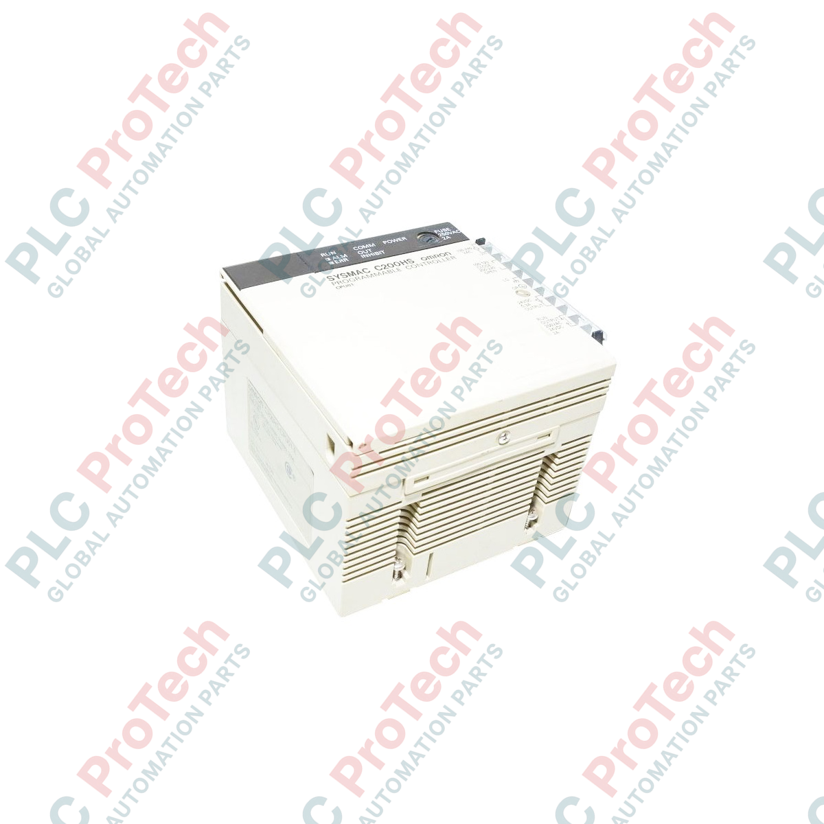
Managing complex localized industrial automation processes, the Omron C200HS-CPU01 functions as a high-performance central processing unit within the legacy Sysmac C200H platform. Designed to execute ladder logic programs with high efficiency, this controller features an integrated program capacity of 15,200 words and a dedicated Data Memory (DM) area of 3,000 words. It is designed to mount directly into standard C200H-BC series backplanes and supports up to 800 local and expansion I/O points, making it ideal for maintaining and scaling existing assembly line, packaging, and material handling systems without requiring full system re-engineering.
Features
-
Optimized Memory Capacity: Provides 15,200 words of program capacity and 3,000 words of DM area to handle complex instruction sets.
-
Broad I/O Capabilities: Supports up to 800 maximum I/O points when configured with compatible expansion modules and backplanes.
-
System Compatibility: Installs directly into Omron C200H-BC series backplanes for easy retrofitting.
-
Data Preservation: Equipped with an internal battery backup system to safeguard volatile memory and register status during power interruptions.
-
Standard Programming: Utilizes standard ladder logic programming languages via Sysmac support software.
Applications
- Factory automation systems utilizing existing Omron C200H hardware architectures.
- Conveyor and material handling control sequences.
- Packaging machinery and product positioning equipment.
- Retrofits, hot-swaps, and hardware lifecycle extension in heavy industrial environments.
Technical Specifications
| Manufacturer |
Omron |
| Model Number |
C200HS-CPU01 |
| Series |
Sysmac C200HS |
| Product Type |
Programmable Controller CPU Module |
| Program Capacity |
15,200 words |
| Data Memory (DM) Area |
3,000 words |
| Expansion Memory (EM) |
None |
| Maximum I/O Capacity |
800 points (using expansion backplanes) |
| Built-in RS-232C Port |
No |
| Programming Language |
Ladder Logic |
| Mounting Interface |
C200H-BC Series Backplane |
| Battery Backup |
Yes (Requires periodic battery maintenance) |
| Shipping Weight (Calculated) |
2.0 kg |
Empirical Engineering Insights
Alternative Models & Compatibility
The C200HS-CPU01 serves as a high-speed upgrade over legacy C200H-CPU01 modules. While physical mounting layouts are identical, note that instruction execution times are significantly faster on C200HS models. If upgrading, carefully review time-dependent subroutines and pulse instruction loops, as the reduced scan times may require adjustment within your ladder program to ensure identical peripheral response.
Application Pitfalls & Engineering Notes
This CPU does not feature a built-in RS-232C port or support internal option boards directly. If serial communications or host computer linkages are required, you must integrate a dedicated Host Link Unit (such as the C200H-LK201-V1) or an ASCII Module on the backplane. Ensure the backplane's power supply unit provides sufficient current output to handle the CPU and all peripheral cards simultaneously.
Commissioning & Wiring Tips
Always perform a complete RAM upload (program and DM registers) via CX-Programmer or a Handheld Programming Console before attempting a CPU replacement. A low-battery indicator on the front panel indicates the memory-backup battery (typically 3G2A9-BAT08) requires physical replacement. Replace the battery only while the controller is powered on, or within 5 minutes of powering down, to prevent memory loss.
Installation Guidelines
CRITICAL WARNING
Isolate and disconnect all external AC and DC power supplies connected to the rack assembly before installing or removing the CPU module. Working on a live system poses severe risks of electrical shock, controller backplane damage, or unexpected industrial machinery actuation.
-
1
Ensure the power supply unit (PSU) mounted to the C200H backplane is fully de-energized and wait for all status indicators to turn off completely.
-
2
Align the CPU module's upper and lower mounting hooks with the corresponding slot guides on the backplane.
-
3
Carefully press the module inward until the multi-pin connector on the rear of the CPU seats firmly and completely into the backplane bus socket.
-
4
Lock the upper and lower retaining clips to prevent vibration-induced connection failure. Reapply power and verify that the 'RUN' LED illuminates status.