Description
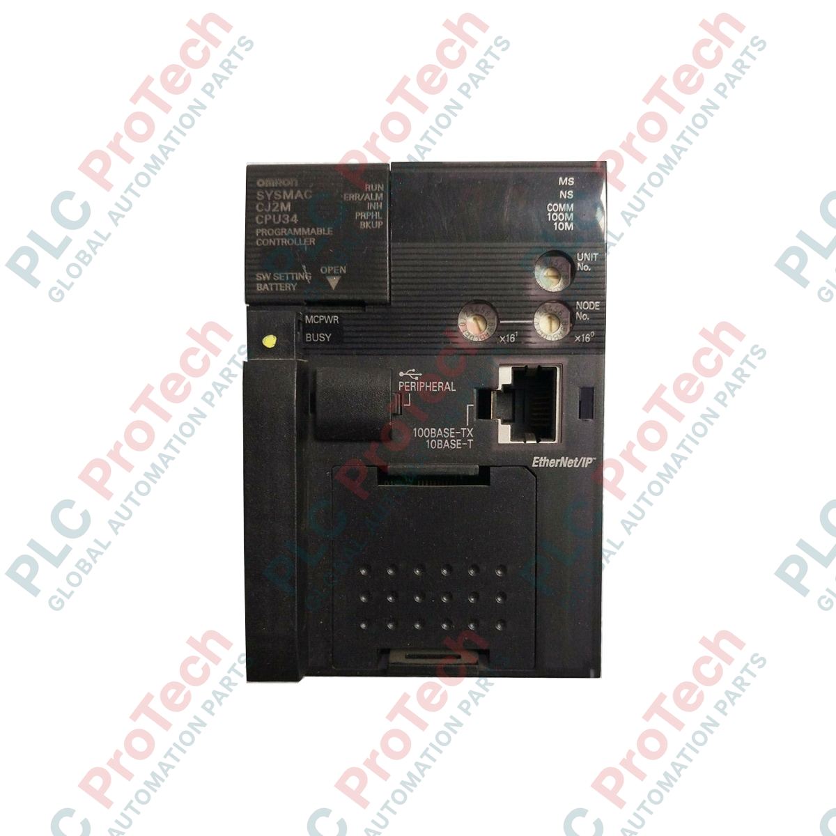
To deliver high-speed logic execution and integrated factory network communications, the Omron CJ2M-CPU34 functions as a core processing module within the modular CJ2M Series PLC architecture. Engineered for high-speed industrial automation, this CPU supports 30K steps of program memory and up to 160K words of data memory. It features an integrated EtherNet/IP port alongside a dedicated USB programming port, eliminating the need for specialized external communication adapters. Its exceptionally fast 0.04 us LD instruction execution speed makes it highly suitable for demanding motion, packaging, and process sequencing tasks.
Key Features
-
High-Speed Processing: Logic execution speed of 0.04 us for basic instructions and 0.06 us for double-precision instructions.
-
Integrated Communication: Built-in EtherNet/IP port for seamless tag data links, message communications, and FINS TCP/IP connections.
-
Expandable Architecture: Supports up to 2,560 local digital I/O points and up to 40 I/O modules across 3 expansion racks.
-
Flexible Memory Allocations: 30K steps program capacity and 160K words of data memory, featuring DM and multiple EM banks.
-
Direct Programming Access: Standard high-speed USB 2.0 peripheral port on the front panel for rapid software monitoring and updates.
Applications
-
Packaging and Labeling: Synchronized operations with multi-station control and high-speed registration.
-
Material Handling: Distributed sorting conveyor networks, automated storage and retrieval systems (AS/RS).
-
Assembly and Testing: Precision electronic assembly machines, pick-and-place stations, and diagnostic instrumentation.
-
Process Control Integration: Remote telemetry, environmental monitoring, and factory-wide SCADA data aggregation.
Technical Specifications
| Manufacturer |
Omron |
| Model |
CJ2M-CPU34 |
| Series |
CJ2M (Built-in EtherNet/IP) CPU Units |
| Program Capacity |
30K steps |
| Data Memory Capacity |
160K words (DM: 32K words, EM: 32K words x 4 banks) |
| LD Instruction Execution Time |
0.04 us |
| Max Local I/O Points |
2,560 points |
| Mountable Units (Expansion Racks) |
40 Units (Maximum 3 Expansion Racks) |
| Current Consumption (5 VDC) |
0.7 A |
| Interfaces |
EtherNet/IP (RJ45), USB (Type-B), Option Board Slot |
| CPU Unit Dimensions |
90 mm x 75 mm x 62 mm |
| Weight |
0.19 kg |
| Shipping Weight (Calculated) |
1.50 kg |
Connections and Interfaces
| Port / Connector |
Function / Cable Specification |
| EtherNet/IP Port |
RJ45, 100Base-TX/10Base-T. Supports Tag Data Links, FINS messages, and FTP server functions. |
| USB Port |
USB 2.0 Type-B connection. High-speed engineering connection for CX-Programmer upload/download. |
| Serial Option Slot |
Accepts optional RS-232C (CP1W-CIF01) or RS-422A/485 (CP1W-CIF11/CIF12-V1) serial option boards. |
Empirical Engineering Insights
Alternative Models & Compatibility
The CJ2M-CPU34 is a direct fit-form-function replacement for legacy CJ1M-series installations, offering greater execution speed and native EtherNet/IP capabilities. Programs from CJ1M platforms can be systematically imported using CX-Programmer, though variables allocated to specific legacy registers should be verified against the extended EM banks of the CJ2M.
Application Pitfalls & Engineering Notes
While the integrated EtherNet/IP port supports heavy traffic, the internal processor prioritizes logic execution over network task allocation. High tag data link rates (over 3200 PPS cumulative) can lead to microsecond fluctuations in task cycle times. If high cyclic network throughput is expected alongside intense floating-point math, segmenting communications onto a dedicated CJ1W-EIP21 module is highly recommended.
Commissioning & Wiring Tips
The node address of the integrated EtherNet/IP interface is assigned via physical rotary switches located on the front panel of the CPU. If the IP address does not resolve, check that these hardware switch settings correspond directly to the host portion of the network IP configuration. Always run Ethernet cables distinct from high-voltage AC motor lines to avoid physical layer noise disruption.
Installation Guidelines
CRITICAL WARNING: De-energize all primary and secondary power distribution systems connected to the CJ-series backplane before inserting or removing the CPU unit. Working on energized backplanes can cause memory corruption, damage internal components, or lead to unexpected plant machinery operation.
1
Align the hooks on the back of the CPU unit with the DIN rail structure and carefully slide the module into position next to the power supply unit.
2
Engage the yellow slider locking clips on both the top and bottom of the unit to lock the assembly firmly to the adjacent modules on the rack.
3
Secure the end plate at the final slot of the assembly to prevent physical lateral drift along the DIN rail.
4
Connect the shielded Ethernet cable (Cat5e or Cat6) to the RJ45 jack and verify the network indicator lamps light up on power-up initialization.