Description
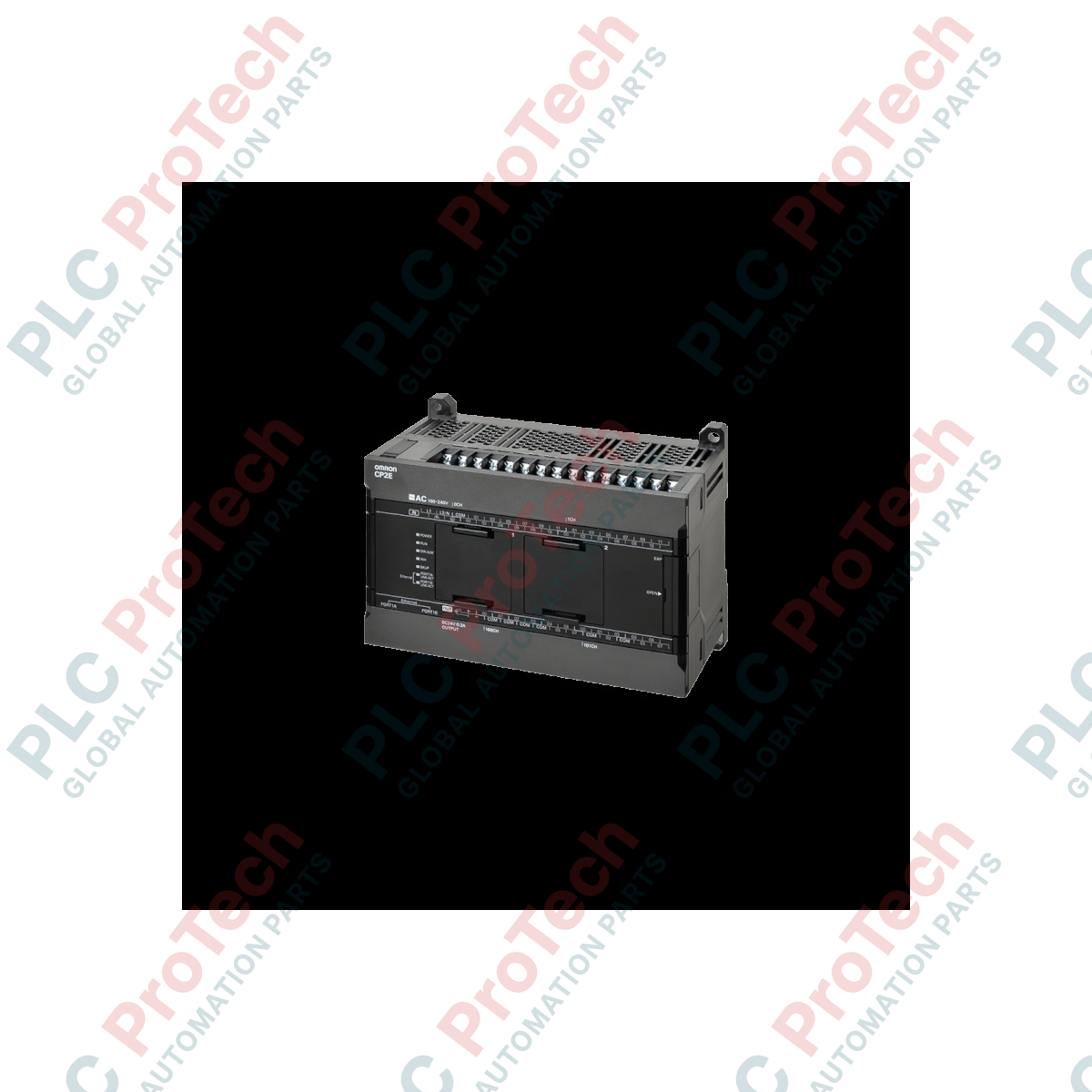
Engineered for modern industrial internet of things (IIoT) architectures, the Omron CP2E-N40DR-D programmable logic controller serves as a highly efficient, network-connected CPU unit designed for compact machinery and distributed automation systems. By integrating dual built-in Ethernet ports with switching capabilities, this controller eliminates the need for external network switches, simplifying line topologies and reducing hardware footprints. The processor features 40 built-in digital I/O points (comprising 24 inputs and 16 relay outputs) alongside a maintenance-free battery-less backup system, ensuring continuous uptime in harsh manufacturing environments.
Key Features
-
Integrated Ethernet Switch: Dual RJ45 ports facilitate direct daisy-chain Ethernet networks for peer-to-peer data links and HMI monitoring.
-
High-Speed Processing: Equipped with high-speed counter inputs up to 100 kHz for rapid positioning and frequency measurement.
-
Maintenance-Free Design: Program memory and standard data are securely backed up in flash memory, removing the vulnerability of battery failure.
-
Expandable I/O Capacity: Supports option board slots to add serial communication (RS-232C, RS-422A/485) or analog feedback modules without increasing the unit width.
Applications
- Decentralized pumping and water treatment instrumentation panels.
- Conveyor networks and packaging machine coordination.
- HVAC, environmental chambers, and building automation controllers.
- Specialized material handling and sorting equipment.
Technical Specifications
| Parameter |
Specification Value |
| Manufacturer |
Omron |
| Model Number |
CP2E-N40DR-D |
| Series Name |
CP2E Series (Network Type) |
| Power Supply Voltage |
24 VDC (Acceptable range: 20.4 to 26.4 VDC) |
| Internal Current Consumption |
0.39 A at 5 VDC / 0.09 A at 24 VDC |
| Built-in Program Capacity |
10K steps |
| Data Memory Capacity |
8K words |
| Total Built-in I/O Points |
40 points |
| Digital Inputs |
24 points (24 VDC, compatible with sink or source wiring) |
| Digital Outputs |
16 points (Relay outputs, 2 A max per common) |
| Communication Interfaces |
2x RJ45 Ethernet Ports (10/100 Mbps), 1x USB 2.0 Type-B Port |
| Operating Temperature |
-20 to 60 degC |
| Shipping Weight (Calculated) |
2.0 kg (including commercial protective packaging) |
Alternative Models & Compatibility
The CP2E network controller replaces legacy CP1E-N series units with matching structural mounting spacing. Note that user programs written for the CP1E can be migrated to the CP2E architecture using the CX-Programmer software conversion tools. However, instruction processing execution speeds are significantly accelerated on the CP2E, which may require you to re-verify critical hardware timing loops and high-speed interruption sequences during commissioning.
Application Pitfalls & Engineering Notes
When utilizing the integrated relay outputs for inductive loads (such as heavy-duty contactor coils or solenoids), you must install external surge suppressors (CR filters for AC loads, diodes for DC loads) directly across the load terminals. Failing to suppress high-voltage counter-electromotive force will cause contact welding or micro-arcs that severely degrade the electrical lifespan of the built-in mechanical relays.
Commissioning & Wiring Tips
To optimize data transmission reliability in environments with high electromagnetic interference, use double-shielded Category 5 (or higher) Ethernet cabling. Ground the functional ground terminal of the controller to a dedicated noise ground plane (Class D grounding with resistance below 100 ohms). Ensure that your input signal wires do not run in the same wire duct as high-voltage AC power lines to prevent signal coupling and false input triggers.
Installation Guidelines
CRITICAL WARNING: HIGH VOLTAGE SAFETY HAZARDS
Always isolate all power sources supplying both the internal CPU electronics and the field relay circuits before handling terminal blocks or attempting mounting procedures. Failure to perform complete electrical de-energization can result in catastrophic equipment damage, electric shock, or physical injury.
1
Mount the controller to a clean, standardized 35mm symmetrical DIN rail inside a protective industrial enclosure (IP54 rated minimum).
2
Ensure a minimum spatial clearance of at least 20mm above, below, and to the sides of the unit to support natural convection cooling currents.
3
Terminate the input power supply to the designated 24 VDC terminals using appropriate bootlace ferrules with a tightening torque of 0.5 N-m.