Description
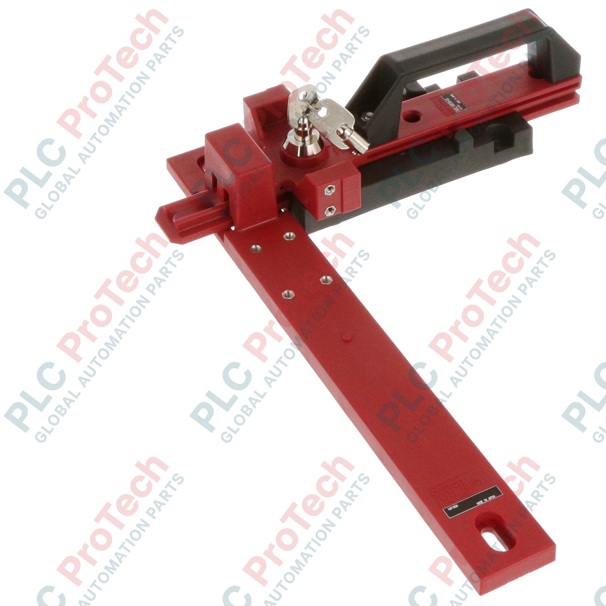
Designed to integrate directly into automated perimeter guarding setups, the Omron D4SL-NSK10-LK slide key unit provides mechanical lockout protection to prevent personnel entrapment within hazardous industrial areas. This lightweight slide key is engineered to work in conjunction with vertical Omron D4SL-N series guard lock safety-door switches, streamlining mounting on standard structural profiles. Constructed from high-strength plastic, it is ideal for securing lightweight access doors, gates, and removable panels while maintaining strict compliance with machinery safety guidelines.
Features
-
Trapped Key Protection: Includes two physical lockout keys to prevent accidental restart of machinery while maintenance personnel are inside the hazard zone.
-
Aluminum Frame Integration: Tailored for direct mounting onto standard 40 mm x 40 mm aluminum profile frames without complex machining.
-
High Mechanical Durability: Rated for a minimum of 20,000 mechanical operations, ensuring long-term field reliability.
-
Complete Installation Kit: Packaged with the essential D4SL-NK1 operation key, mounting plate, lockout key strap, and specialized mounting screws.
-
Dual-Language Safety Labels: Supplied with English and Japanese caution stickers to clearly communicate locking states to operators.
Applications
- Robot work cells and robotic welding enclosures.
- Automated packaging and material handling lines.
- Lightweight machine tool protective guarding.
- Semi-conductor and electronics assembly enclosure doors.
Technical Specifications
| Specification Parameter |
Value / Rating |
| Manufacturer |
Omron |
| Model Number |
D4SL-NSK10-LK |
| Compatible Switch Series |
Omron D4SL-N Guard Lock Safety Switches |
| Mechanical Durability |
20,000 operations minimum |
| Material |
Plastic (optimized for lightweight doors) |
| Frame Mounting Compatibility |
40 mm x 40 mm aluminum frame |
| Included Operation Key |
D4SL-NK1 (1 qty) |
| Lockout Keys Included |
2 qty (with 1 strap) |
| Device Net Weight |
Approx. 0.6 kg |
| Shipping Weight (Calculated) |
1.5 kg |
Empirical Engineering Insights
Alternative Models & Compatibility
The D4SL-NSK10-LK is specifically matched to the physical stroke and structural dimensions of the D4SL-N series vertical safety switches. It cannot be used interchangeably with legacy, non-N D4SL models due to subtle variances in mounting plate alignment, screw boss spacing, and operation key insertion paths. Always verify the suffix designation of your existing door switch before deployment.
Application Pitfalls & Engineering Notes
Because this slide key features a high-grade plastic housing, it must not be installed on heavy steel sliding doors or in process zones subjected to extreme high-velocity vibration or thermal cycling. Misalignment of heavy doors during closure can stress the guide key, resulting in premature mechanical failure of the sliding arm or the D4SL-NK1 target key.
Commissioning & Wiring Tips
To ensure the mechanical durability target of 20,000 cycles is achieved, mechanical alignment should be manually verified before final torque is applied to the mounting plate screws. There must be no binding or rubbing as the operation key inserts into the guard switch mouth. Utilize the supplied special mounting screws to prevent unauthorized removal of safety hardware.
Installation Guidelines
CRITICAL WARNING
Disconnect and lock out all electrical control power supplying the D4SL-N safety switch before starting installation. Do not bypass or alter any safety interlocking circuits during mounting. Failure to observe proper lock-out procedures can lead to mechanical crushing, entrapment, or severe personal injury.
1
Align the D4SL-N mounting plate directly to the 40 mm x 40 mm aluminum frame profile and secure it tightly using appropriate structural fasteners.
2
Mount the vertical D4SL-N safety door switch to the installed mounting plate using the three supplied specialized safety mounting screws.
3
Fix the D4SL-NK1 operation key to the sliding door frame using the two provided specialized mounting screws. Ensure the guide is perfectly squared.
4
Manually slide the guard door to verify smooth insertion of the operation key into the switch head. Apply the caution labels to the designated guard area.