Description
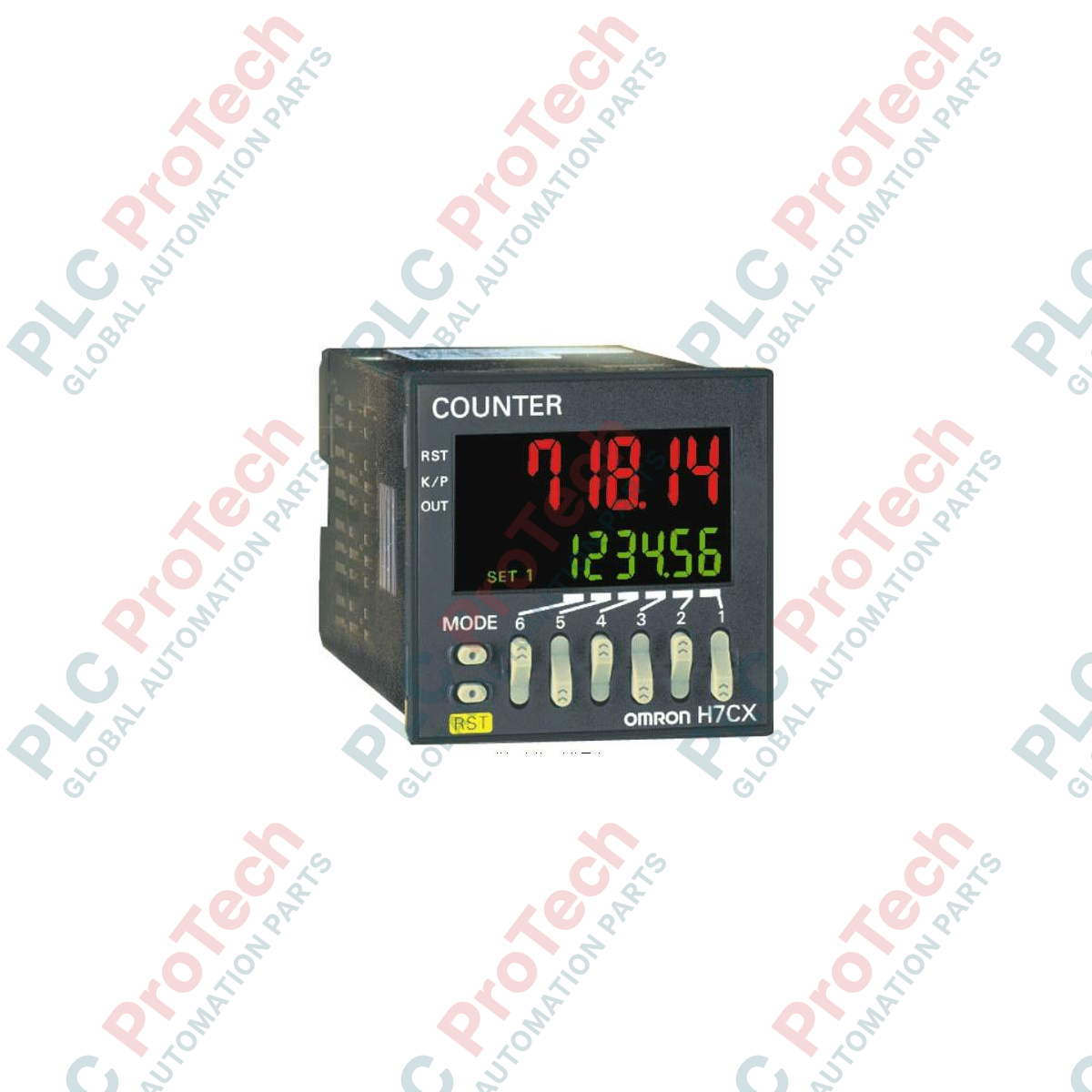
Designed for seamless integration into standard DIN 48 x 48 mm panel cutouts, the Omron H7CX-R11W-N operates as a highly reliable industrial digital tachometer. Powering directly off a 100 to 240 VAC supply, this 6-digit unit features a multi-stage monitoring architecture factory-configured with 2-stage limits. This allows operators to easily manage independent high/low threshold limits on rotational, linear, or cycle speed systems.
Key Features
-
Multi-Stage Thresholds: Built with a 2-stage (W-type) configuration to handle multiple control actions or alerts.
-
Versatile Outputs: Supports standard contact output or combined contact/transistor outputs to link with PLCs or safety interlocks.
-
11-Pin Plug-in: Connects via an industry-standard 11-pin base layout, allowing hot-swapping and simplifying cabinet wire routing.
-
High-Visibility Display: Clear digital layout with configurable green/red visual color switching to denote fault/warning conditions.
Applications
- Conveyor speed monitoring and linear product-per-minute calculations.
- Rotational shaft speed (RPM) tracking on heavy motors, pumps, and fans.
- Flow and cycle rate calculations in batching operations.
Technical Specifications
| Manufacturer |
Omron |
| Model Number |
H7CX-R11W-N |
| Product Type |
Multifunction Tachometer |
| External Connection |
11-Pin Socket |
| Display Digits |
6 Digits |
| Setting Type |
2-Stage Setting (W) |
| Output Options |
Contact / Contact + Transistor |
| Supply Voltage |
100 to 240 VAC (50/60 Hz) |
| Dimensions |
4.8 cm x 4.8 cm x 8.41 cm |
| Shipping Weight |
2.0 kg (Including packaged accessories) |
Empirical Engineering Insights
Alternative Models & Compatibility
When replacing legacy, non-N revision tachometers, the outer housing dimensions match standard 48x48 cutouts, but the back panel clearance must be verified. The upgraded "-N" series features optimized tactile configuration keycaps and updated internal display firmware for faster response times. Pin layout configurations remain retrocompatible on existing 11-pin bases.
Application Pitfalls & Engineering Notes
A frequent installation pitfall involves neglecting the input frequency limits. Setting a high-speed proximity sensor or rotary encoder on the default 30 Hz contact-bounce filter will result in delayed counts or missing input pulses. Toggle the software filter parameter up to the 10 kHz limit for high-speed switching tasks.
Commissioning & Wiring Tips
To prevent electromagnetic interference (EMI) from distorting high-speed input pulse signals, run shielded twisted-pair (STP) cabling for the tachometer's sensor lines. Ensure the shield is terminated strictly at the panel ground side and never run signal wires parallel with heavy high-voltage motor output lines.
Installation Guidelines
CRITICAL WARNING: Ensure the main power supply line (100 to 240 VAC) is fully isolated and verified dead before attempting to insert or remove the controller from the 11-pin base. Unplanned hot-plugging can cause localized contact arcing and permanent damage to internal switching circuits.
1
Securely mount the 11-pin front-connecting or back-connecting socket onto the DIN rail inside the enclosure.
2
Wire the power feed, sensor pulse inputs, and control outputs following the schematic diagram on the side of the housing.
3
Align the guide notch on the device plug with the socket keyway, pushing in firmly until it sits completely flush.
4
Energize the circuit, configure the required sensor type, and calibrate the scale parameters via the front panel buttons.