Description
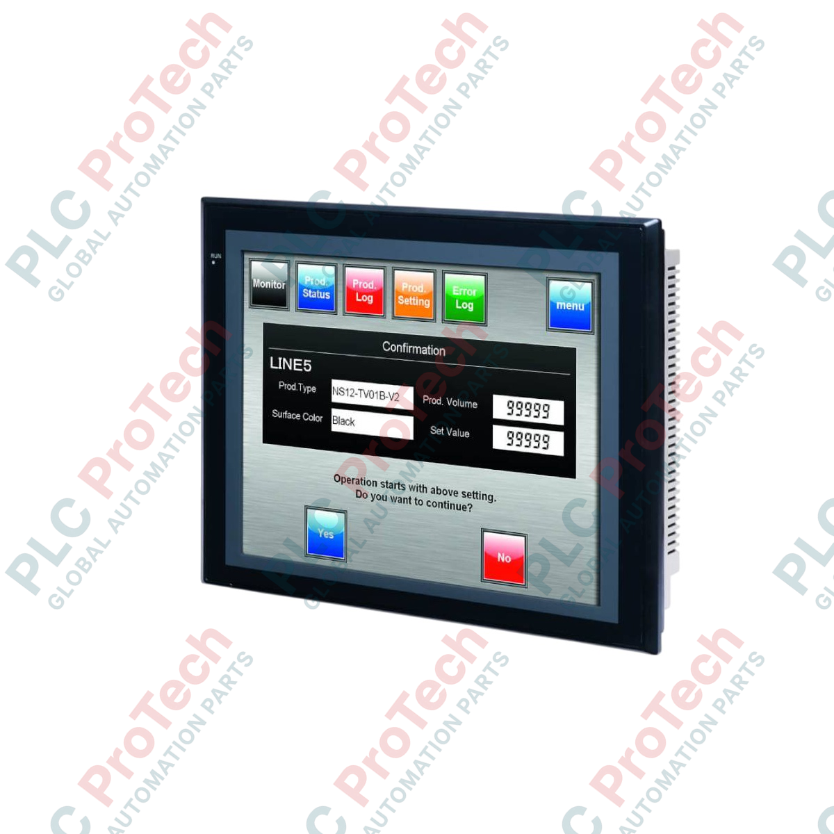
Providing dedicated human-machine visualization, the Omron NS10-TV00B-V1 serves as a high-resolution graphical operator interface designed for real-time monitoring and control inside automated industrial systems. This model features a robust 10.4-inch TFT active matrix display integrated with a highly responsive touchscreen interface, enabling intuitive system diagnostics and process management. Encased in a black bezel housing, the device is engineered with built-in serial and USB ports to ensure seamless connectivity within multi-node PLC architectures.
Features
- High-durability TFT color LCD screen displaying up to 256 colors for clear, high-contrast diagnostics.
- Dual integrated RS-232C serial communication ports enabling direct, simultaneous PLC and peripheral interfacing.
- Dedicated CompactFlash slot for automated screen project backup, event logging, and recipe data storage.
- USB host and slave interfaces supporting seamless PC programming via CX-Designer and auxiliary data transfer.
- Modular expansion capability via dedicated rear-panel option slot for Ethernet or Controller Link modules.
Applications
- Automotive body shop assembly lines and conveyor system visualization.
- Packaging machinery, palletizers, and material handling systems.
- Water treatment processing and pump control monitoring stations.
- Food and beverage batching, mixing, and heating processes.
Technical Specifications
| Manufacturer |
Omron |
| Model Reference |
NS10-TV00B-V1 |
| Display Type |
TFT Color Active Matrix LCD |
| Screen Size (Diagonal) |
10.4 inches |
| Resolution |
640 x 480 pixels (VGA) |
| Display Colors |
256 colors |
| Rated Input Voltage |
24 VDC |
| Allowable Voltage Range |
20.4 to 27.6 VDC |
| Power Consumption |
25 W maximum |
| Serial Communications |
2 x RS-232C ports (9-pin D-sub) |
| USB Ports |
1 x USB Type B (Slave, USB 1.1) |
| Expansion Slot |
1 x Slot (for network interfaces or video input board) |
| Storage Medium |
CompactFlash Slot (Type I/II) |
| Operating Temperature |
0 to 50 degC |
| Ambient Humidity |
35% to 85% RH (non-condensing) |
| Bezel Color |
Black |
| Shipping Weight (Calculated) |
3.5 kg |
Connections and Interfaces
| Interface Connection |
Physical Connector |
Signal / Function Assignment |
| Serial Port A |
9-pin D-sub (Female) |
Host Link / NT Link (1:1 or 1:N) protocol interface |
| Serial Port B |
9-pin D-sub (Female) |
Host Link, NT Link, or temperature controller serial link |
| USB Slave |
USB Type B |
Direct PC programming and screen data transfer |
| Power Terminals |
3-position terminal block |
24 VDC (+), 0 VDC (-), Functional Ground (GR) |
Empirical Engineering Insights
Alternative Models & Compatibility
The legacy non-V1 version and the updated V1 module are mount-compatible, utilizing identical cabinet cutouts. Note that screen projects compiled for V1 hardware require updating the target HMI system program in CX-Designer before performing a serial or USB download to prevent runtime initialization faults.
Application Pitfalls & Engineering Notes
Thermal behavior inside small, unventilated enclosures can accelerate backlight aging. Always maintain a minimum clearance of 100 mm around all rear chassis surfaces. Do not use standard consumer-grade MLC CompactFlash cards; write endurance limits will trigger localized sectors to corrupt under heavy data-logging cycles. Standardize on SLC industrial-grade media.
Commissioning & Wiring Tips
When wiring high-speed NT Link serial configurations over long distances, route serial runs strictly away from high-current AC motor leads to reduce electromagnetic interference. Ground loops are common if functional ground terminals are bridged back to industrial drive bus commons. Ensure functional ground (GR) is terminated directly to the main cabinet star ground plate.
Installation Guidelines
CRITICAL WARNING: ELECTRICAL RISK
Isolate and lock out all AC/DC power sources feeding the enclosure panel prior to preparing cutouts, executing physical installation, or terminating control wiring. Failure to do so may result in device damage, internal circuit failure, or high-voltage shock.
1
Prepare Panel Cutout: Trace and cut a clear rectanglar opening of 302.0 mm x 228.0 mm (tolerance +1.0 / -0.0 mm) in the enclosure door. Ensure panel thickness is between 1.6 mm and 4.8 mm.
2
Verify Bezel Gasket: Confirm that the waterproof rubber sealing gasket is seated flat inside the outer perimeter groove of the HMI bezel. This is critical to maintain IP65-equivalent protection.
3
Secure Mounting Brackets: Insert the device from the front of the panel cutout, then slide the mounting brackets into the side tracks from behind. Progressively tighten the screws with a torque of 0.5 to 0.6 N-m to ensure an even seal without cracking the bezel.
4
Terminate Power & Ground: Connect 24 VDC power lines using 2 mm2 cross-section wires. Wire the Functional Ground terminal using a green/yellow earth lead directly to the main system electrical ground point.