Description
Positioning control within the Sysmac automation platform is seamlessly achieved using this Omron NX-PG0112 1-channel pulse output unit. Integrating directly with NX-series CPU units or EtherCAT coupler units, this module provides reliable open-loop control for stepper motor drives and servo systems accepting pulse-string commands. Designed with an open collector NPN interface, it supports high-speed processing with synchronous refreshing to align positioning tasks precisely with the primary network controller cycle.
Key Features
-
Synchronous I/O Refreshing: Synchronizes output timing directly with the EtherCAT network cycle to eliminate jitter and timing drift in multi-axis setups.
-
Dual Output Formats: Configurable for either Forward/Reverse pulse outputs or Pulse/Direction pulse outputs to accommodate various driver input topologies.
-
Integrated Local I/O: Outfitted with 2 dedicated external inputs (e.g., origin, limit, or latch signals) and 3 physical outputs to manage local drive states.
-
Toolless Connection: Uses a 16-point screwless clamping terminal block, which significantly accelerates cabinet assembly and minimizes vibration-induced wiring failures.
-
Ultra-Compact Profile: The slim 12 mm width saves valuable space on standard DIN-rail assemblies.
Industrial Applications
-
Packaging Machinery: Accurate indexing, feeding, and rotary indexing table positioning.
-
Semiconductor Processing: Highly repeatable wafer handling and position positioning in cleanroom gantry setups.
-
Feeder Systems: Dynamic speed and position control of stepping motors in automated sorting and parts feeding applications.
Technical Specifications
| Parameter |
Specification Value |
| Manufacturer |
Omron |
| Model Number |
NX-PG0112 |
| Series |
NX Series |
| Number of Channels |
1 Channel |
| Output Type |
Open Collector (NPN Type) |
| Maximum Pulse Speed |
500 kpps |
| Position Control Range |
-2,147,483,648 to 2,147,483,647 pulses |
| Velocity Control Range |
1 to 500,000 pps |
| Integrated Inputs |
2 Points (External input signals) |
| Integrated Outputs |
3 Points (Forward/Reverse pulse, plus 1 general external output) |
| I/O Refresh Method |
Synchronous I/O refreshing / Task period prioritized refreshing |
| External Connection |
Screwless clamping terminal block (16 terminals) |
| I/O Power Consumption |
20 mA maximum |
| Maximum Cable Length |
3 meters (for pulse output lines and I/O lines) |
| Dimensions (W x H x D) |
12 mm x 100 mm x 71 mm |
| Net Weight |
0.07 kg |
| Shipping Weight (Calculated) |
1.00 kg (with protective packaging) |
Connections and Interfaces
The 16-point push-in terminal layout on the front of the NX-PG0112 handles the distribution of DC power, input switches, and driver command paths. Ensure proper separation of high-frequency pulse lines from main power circuits.
| Terminal Assignment |
Signal Name |
Function / Circuit Details |
| A1 / B1 |
I/O PWR + / - |
24 VDC external input/output power supply connection |
| A2 / B2 |
IN1 / IN2 |
External input points (Origin detection, proximity, limit, or latching) |
| A3 / B3 |
OUT1 / OUT2 |
Pulse train outputs (Forward / Pulse string) |
| A4 / B4 |
OUT3 / OUT4 |
Direction control outputs (Reverse / Direction control) |
| A5 to A8 / B5 to B8 |
COM / NC |
Common ground returns and internal non-connected safety pins |
Empirical Engineering Insights
Alternative Models & Compatibility
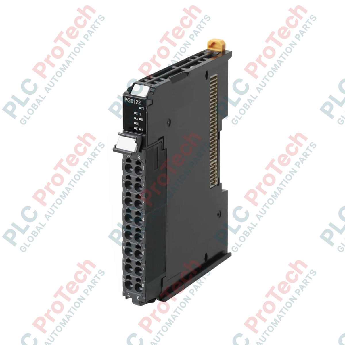
Unlike differential line driver versions (such as the NX-PG0122), the NX-PG0112 relies on open collector NPN hardware. Ensure your stepper or servo drive features integrated or external pull-up options matching your control voltage loop, typically requiring a 24 VDC pull-up path to achieve clean rise and fall times.
Application Pitfalls & Engineering Notes
Because this is an open collector unit, signal integrity degrades rapidly over distance due to line capacitance. Maintain physical cable lengths strictly under 3 meters from the module terminals to the motor drive interface to prevent signal attenuation and missed positioning counts at high pulse frequencies approaching the 500 kpps maximum rate.
Commissioning & Wiring Tips
When configuring Sysmac Studio, register this unit under your EtherCAT Coupler or CPU Rack and assign the Axis parameters under the Motion Control settings. Double-check that your axis variable is configured as a Single-Axis Position Control axis. Always use shielded twisted-pair cables for the command output lines, grounding the shields securely at the drive cabinet entrance.
Installation Guidelines
CRITICAL WARNING
Isolate all power sources supplying the PLC backplane, NX I/O bus, and drive systems before beginning hardware installation or terminal wiring. Hot-plugging or wiring under power will cause irreversible electrical damage to the open collector transistors and void the manufacturer's warranty.
1
Align the hook on the bottom side of the NX-PG0112 unit with the guide rail on the adjacent bus unit, and push forward until the lock clicking sound is heard.
2
Strip your signal wire insulation back by 10 mm. Insert solid wires directly into the terminal holes; for stranded wires, press the release tab using a flat-head screwdriver before insertion.
3
Wire the external 24 VDC supply to terminals A1 and B1 to power the input latch loops and drive output circuits, checking that polarities match precisely.
4
Apply power to the main CPU rack first, verify status LED sequences are green, then power the I/O bus loop.