Description
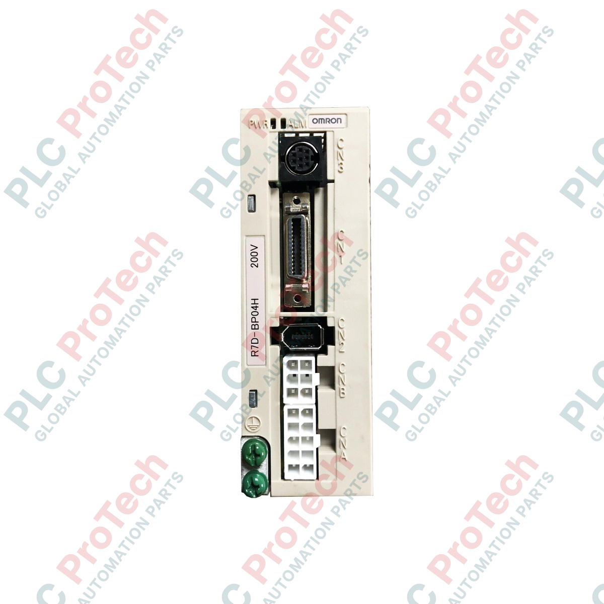
Designed to deliver compact, precise motion control, the Omron R7D-BP04H is a high-performance AC servo drive operating within the SmartStep series framework. It delivers a 400 W power rating with a nominal input voltage of 200 VAC, converting single-phase incoming power into a highly stable output for compatible dynamic servomotors. This drive features an all-digital control system utilizing a high-frequency 12 kHz IGBT-based PWM inverter method, ensuring smooth velocity regulation and precise positioning control in highly active industrial automation environments.
Features
- All-digital processing architecture for rapid control-loop execution and minimal latency.
- Integrated 12 kHz PWM inverter driven by high-efficiency Insulated Gate Bipolar Transistors (IGBTs).
- High-resolution speed feedback system processing 10,000 pulses/revolution from incremental encoders.
- Accepts command pulse responses up to 500 kpps using differential line driver inputs.
- Robust dynamic output current delivering up to 7.8 A during momentary peak torque demands.
Applications
- High-speed pick-and-place material handling gantries.
- Precision electronic assembly and component inserting machinery.
- Cartoning and automated packaging indexing axes.
- Form-fill-seal and labeling machinery feed drives.
Technical Specifications
| Specification Parameter |
Value / Rating |
| Manufacturer |
Omron |
| Model Designation |
R7D-BP04H |
| Power Output Rating |
400 W |
| Compatible Motor Voltage |
200 V |
| Main-Circuit Input Voltage |
Single-phase 200 to 240 VAC (Allowable: 170 to 264 VAC) |
| Input Frequency |
50/60 Hz |
| Continuous Output Current (rms) |
2.5 A |
| Momentary Maximum Current (rms) |
7.8 A |
| Inverter Control Scheme |
All-digital IGBT-based PWM (12 kHz carrier frequency) |
| Feedback Type Compatibility |
10,000 pulses/revolution incremental encoder |
| Command Pulse Response Limit |
Line driver input up to 500 kpps |
| Applicable Servomotors |
G020030H, GP20030H |
| Unit Dimensions (W x H x D) |
40 mm x 175 mm x 120 mm |
| Net Unit Weight |
0.42 kg |
| Shipping Weight (Calculated) |
3.00 kg |
Connections and Interfaces
| Terminal / Connector Block |
Description and Dedicated Assignment |
| L1, L2 Terminals |
Single-phase main power supply inputs (200 to 240 VAC) |
| U, V, W Terminals |
3-Phase output terminals to servomotor stator windings |
| CN1 Connector |
Control I/O port for line driver pulse inputs and command signals |
| CN2 Connector |
Dedicated incremental encoder feedback signal input port |
| Frame Ground Terminal |
Primary system grounding terminal (must connect to low-impedance earth) |
Empirical Engineering Insights
Alternative Models & Compatibility
The R7D-BP04H drive is specifically designed as part of Omron's SmartStep catalog. It is not directly drop-in interchangeable with standard SYSDRIVE units unless tuning configurations and command parameters are systematically migrated. When replacing units, verify that your host controller supports the 500 kpps line-driver pulse output limit defined by this series.
Application Pitfalls & Engineering Notes
This unit is optimized for high-density panel integration, yet its internal thermal profile relies on convective cooling. Ensure the drive is mounted vertically in environments not exceeding 55 Celsius. Operating without the specified clearance of 50 mm above and below the drive chassis can result in localized hot spots and premature failure of the internal DC bus capacitor bank.
Commissioning & Wiring Tips
The internal high-speed switching frequencies (12 kHz) from the IGBT PWM inverter can cause electrical noise in nearby logic signals. It is mandatory to isolate all power connections (U, V, W) from control I/O lines (CN1). Always run high-current motor leads in a separate, grounded metal conduit to avoid induction of ghost pulses on adjacent sensor cables.
Installation Guidelines
CRITICAL WARNING: Prior to attempting installation, wiring verification, or hardware swapping, completely de-energize the main AC incoming power line. Wait at least 5 minutes for the internal DC bus capacitors to discharge fully. Verify that the bus voltage has dropped below 30 VDC using an isolated digital multimeter before making physical contact with the terminals.
1
Mechanical Mounting: Fasten the servo drive securely to a flat, rigid metal subpanel inside an IP54-rated or better industrial enclosure. Maintain proper ventilation spacing to ensure unimpeded air movement.
2
Ground Connection: Ground the unit's main frame grounding terminal directly to the enclosure's backplate using a heavy-duty, low-impedance copper strap or grounding conductor.
3
Power Terminals: Wire the single-phase supply lines to L1 and L2 using wire rated for at least 75 Celsius, and connect the corresponding phase outputs (U, V, W) directly to the servomotor.
4
Signal Cabling: Plug in the dedicated encoder feedback cable at the CN2 port, then hook up the command pulse controller cable to CN1, keeping signal cabling physically separated from power lines.