Description
Interfacing serial Modbus networks directly with the Rockwell Automation FLEX I/O backplane is efficiently handled by the ProSoft MV156-MCM Modbus Communication Module. This hardware module functions as a critical bridge, allowing FLEX I/O adapters to exchange industrial data with Modbus RTU or ASCII transmission modes. Operating as either a Master or a Slave, the module provides reliable serial telemetry integration for legacy field instruments, power monitors, and variable speed drives within a rugged, space-saving form factor. Engineers can deploy this module to bypass complex gateway solutions and achieve direct-to-chassis backplane data mapping.
Features
-
Dual-Protocol Support: Full compatibility with Modbus RTU and ASCII protocols in both Master and Slave modes.
-
Backplane Integration: Mounts directly into standard Rockwell Automation FLEX I/O terminal bases.
-
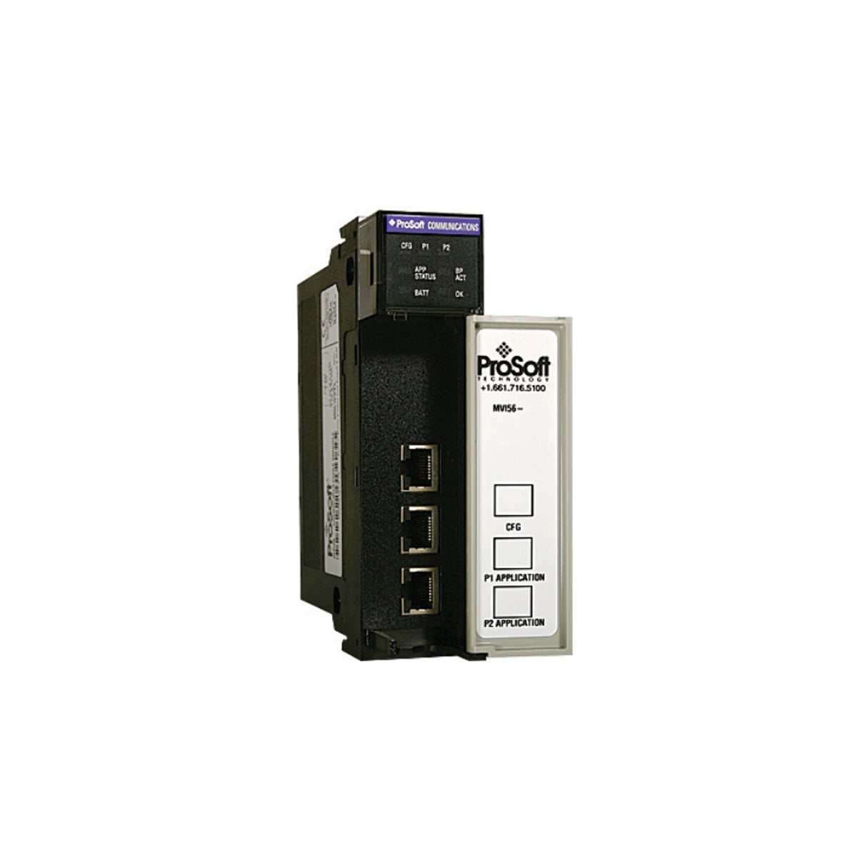
Comprehensive Diagnostic LEDs: Front-panel indicators provide immediate visual feedback on module status, serial activity, backplane transfer rates, and system errors.
-
Dedicated Configuration Port: Features an RJ45 physical serial port (configurable as RS-232 via the supplied DB-9M cable) to simplify local diagnostics and parameters upload.
Applications
-
Power Distribution Systems: Monitoring electrical parameters from digital protective relays and power meters on serial Modbus networks.
-
Oil, Gas, and Petrochemical Plants: Gathering remote custody transfer data from flow computers and RTUs.
-
Process Plant Modernization: Integrating legacy serial transmitter manifolds into newer Ethernet/IP or ControlNet-based FLEX I/O architectures.
Technical Specifications
| Parameter |
Specification Value |
| Manufacturer |
ProSoft Technology |
| Model Number |
MV156-MCM |
| Backplane Current Draw |
800 mA at 5 VDC, 3 mA at 24 VDC |
| Operating Temperature |
0 to 60 degC (32 to 140 degF) |
| Storage Temperature |
-40 to 85 degC (-40 to 185 degF) |
| Relative Humidity |
5% to 95% (non-condensing) |
| Mechanical Vibration |
5 g from 10 to 150 Hz |
| Mechanical Shock |
30 g Operational, 50 g Non-operational |
| CFG (Configuration) Port |
RJ45 (RS-232 physical layer, DB-9M with supplied cable) |
| Diagnostic LEDs |
Module Status, Backplane Transfer Status, Application Status, Serial Activity |
| Shipping Weight |
2.0 kg |
Empirical Engineering Insights
Alternative Models & Compatibility
The MV156-MCM is optimized for mounting onto standard FLEX I/O 1794 terminal bases. Ensure your system's network adapter module (such as Ethernet/IP, ControlNet, or Profibus-DP adapters) has sufficient power headroom, as this module draws significant current compared to digital input blocks.
Application Pitfalls & Engineering Notes
Power Budget Planning: Drawing 800 mA at 5 VDC directly from the backplane can easily overload a standard 1794-APB or 1794-AENT power budget if several analog and communication modules are combined in the same chassis. Always calculate the total chassis backplane current draw to prevent intermittent initialization failures or communication drops.
Commissioning & Wiring Tips
Always use high-quality shielded twisted-pair (STP) cabling for RS-485 Modbus runs. For long serial runs, ensure 120-ohm termination resistors are installed across the TX/RX terminals at the physical ends of the network segments to minimize signal reflections and communication timeouts.
Installation Guidelines
CRITICAL WARNING: Disconnect all power sources before inserting or removing modules from the FLEX I/O backplane. Performing any hardware manipulation under live electrical load can cause component damage, invalid data writes on the Modbus serial bus, or severe localized electrical arcing.
1
Verify that the target 1794 terminal base is securely mounted to the DIN rail and that the backplane interconnect plug is correctly aligned.
2
Align the module guides with the terminal base slot and press firmly down until the module latch clicks into place, locking it onto the base.
3
Connect your RS-232 diagnostic cable to the CFG port or run the RS-485 Modbus field network lines directly to the matching terminals on the base, ensuring proper polarity and shield ground connections.