Présentation du produit
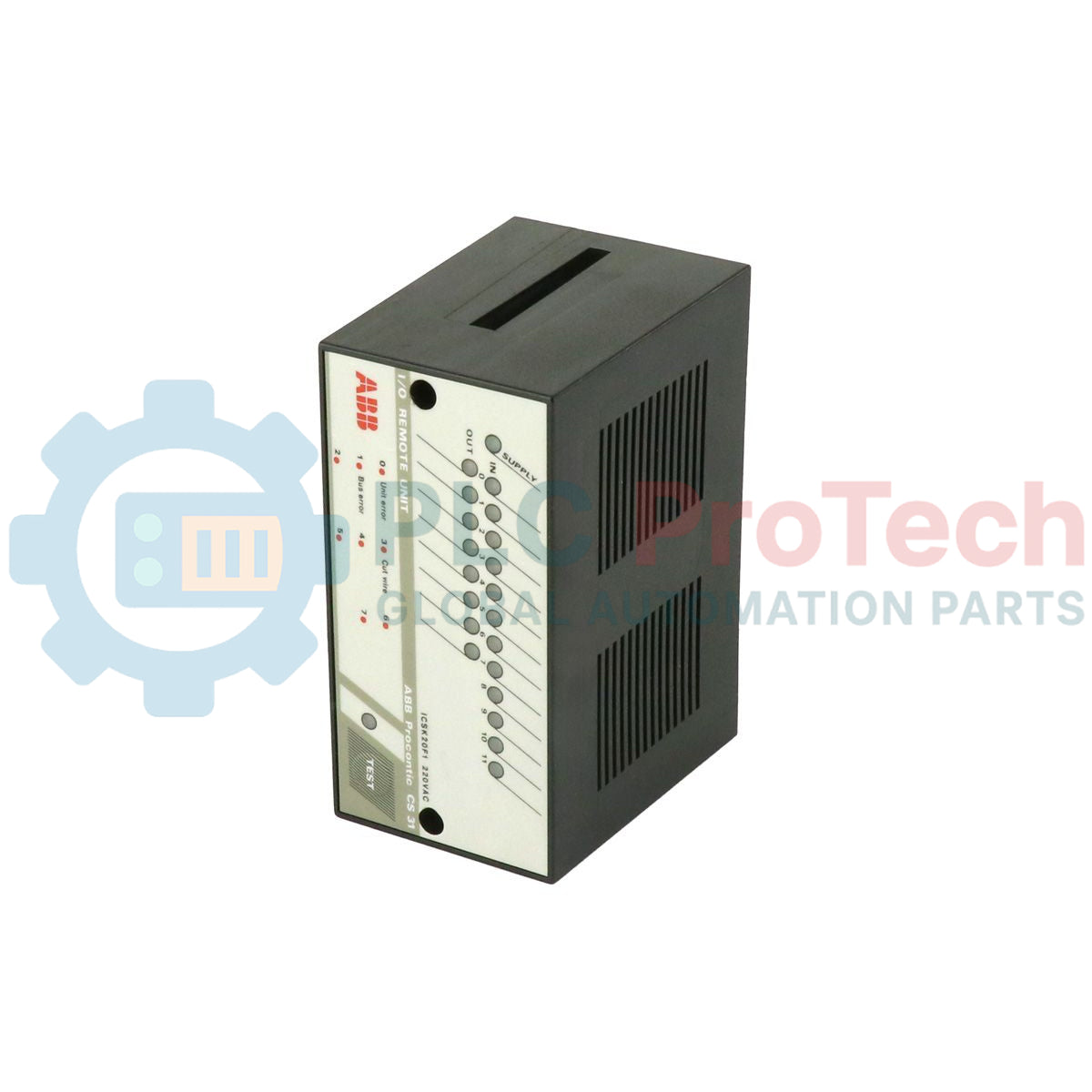
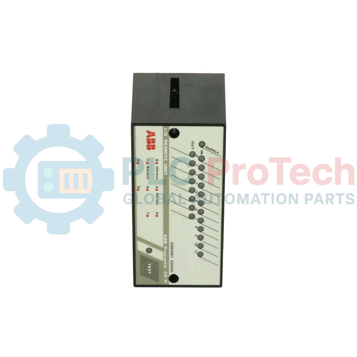
Le FPR3327101R1202 (ICSK 20 F1) est une unité d’entrée/sortie binaire à haute fiabilité conçue pour le système de bus de terrain ABB Procontic CS31.
Ce module d’E/S distribué offre 12 entrées numériques (24 VCC) et 8 sorties relais, créant une interface flexible entre l’automate central et les capteurs et actionneurs de terrain.
Conçu pour une intégration transparente dans le réseau CS31, l’ICSK 20 F1 prend en charge des architectures d’automatisation décentralisées qui réduisent la complexité du câblage et les coûts d’installation.
Ses performances éprouvées sur le terrain en font un choix largement utilisé dans les systèmes de fabrication, d’infrastructure et de contrôle des procédés où une communication rapide et des temps de réponse stables sont essentiels pour un fonctionnement fiable.
Configuration technique
Le FPR3327101R1202 est conçu pour une installation modulaire et une visibilité diagnostique simple :
-
Capacité logique : 12 entrées 24 VCC non isolées et 8 sorties relais supportant jusqu’à 250 VAC / 2 A.
-
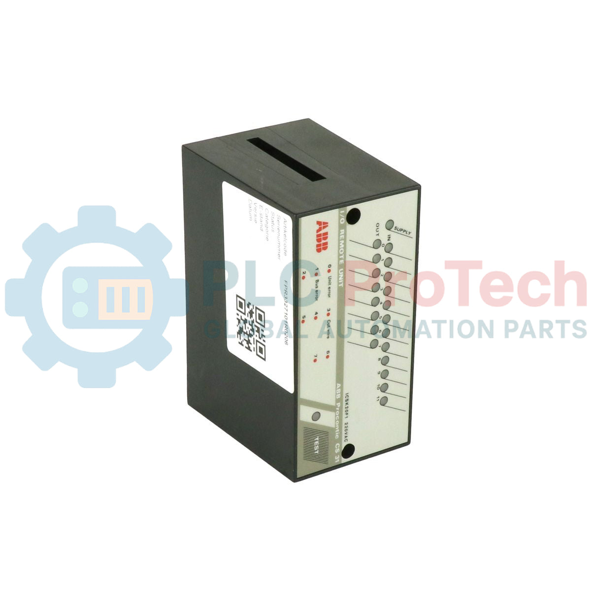
Interface visuelle : Voyants LED comprenant 12 LED d’état des entrées (0–11), 8 LED d’état des sorties (0–7), une LED d’alimentation verte et une LED d’erreur rouge.
-
Diagnostic embarqué : Référence des codes d’erreur imprimée sur le panneau avant, ainsi qu’un bouton-poussoir TEST pour la mise en service et le dépannage.
-
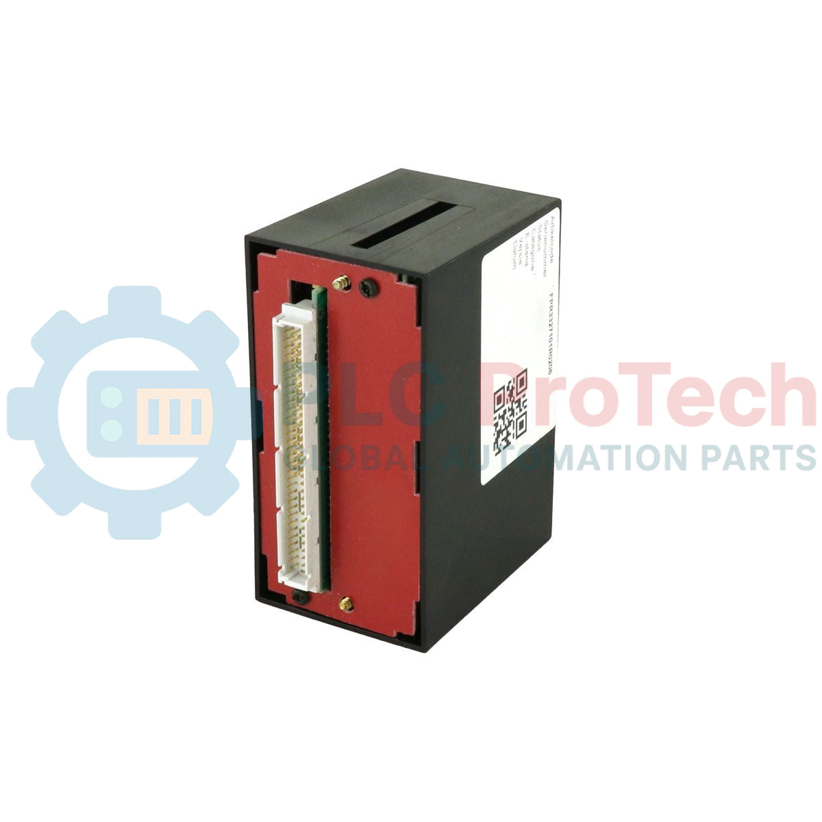
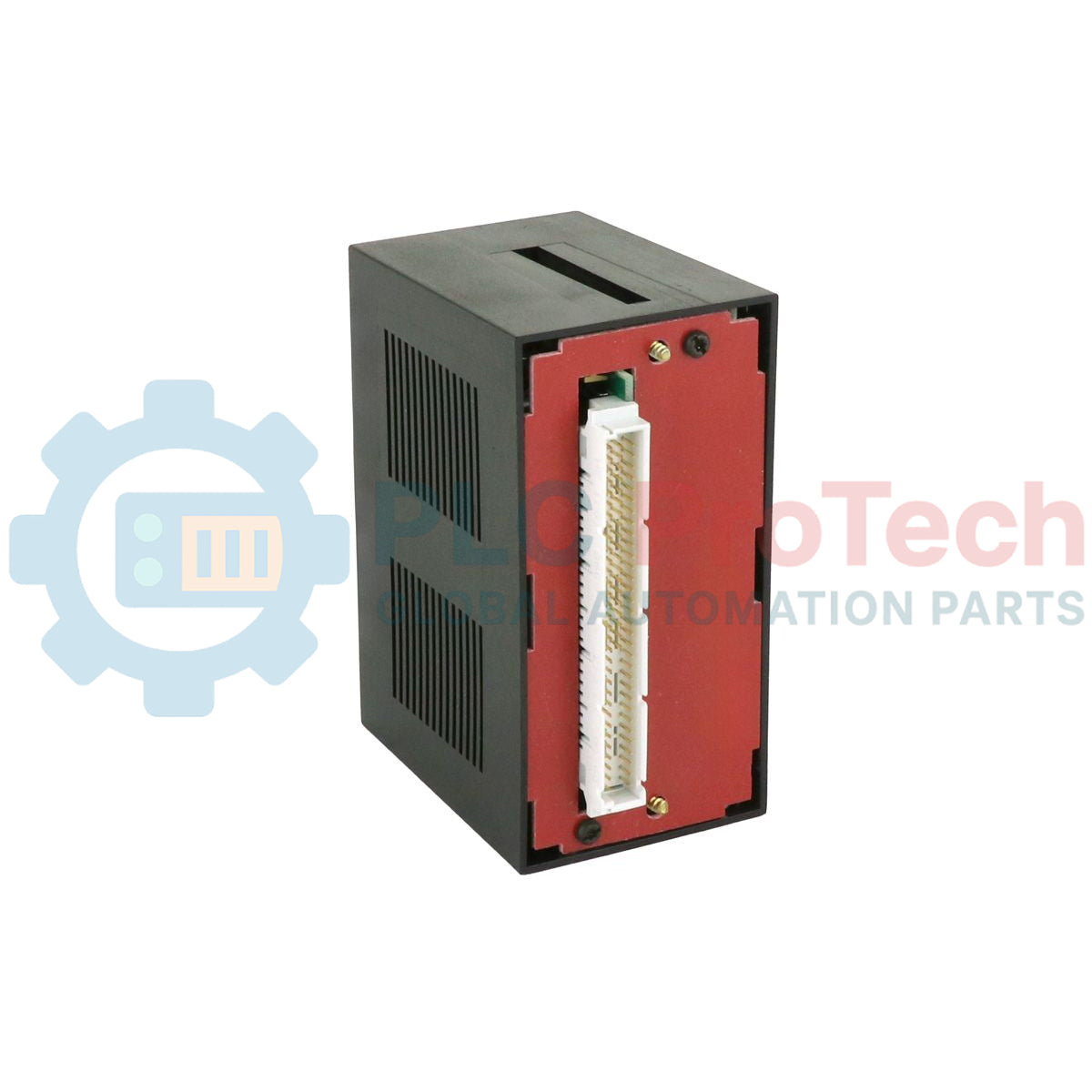
Architecture de montage : Conçu pour une installation sur une base enfichable ECZ, permettant un remplacement rapide du module sans déconnecter le câblage de terrain.
-
Communication bus de terrain : Optimisé pour le protocole CS31 avec un temps de configuration d’environ 452 microsecondes.
Caractéristiques techniques
| Modèle |
ICSK 20 F1 (ICSK20F1) |
| Numéro de commande |
FPR3327101R1202 |
| Marque |
ABB |
| Système de bus de terrain |
Procontic CS31 |
| Alimentation |
24 VCC |
| Consommation de courant |
0,3 A (maximum) |
| Nombre d’entrées |
12 (24 VCC nominal) |
| Nombre de sorties |
8 (Relais, 250 VAC / 2 A) |
| Délai d’entrée |
5 ms |
| Montage |
Base enfichable ECZ |
| Poids |
0,25 kg |
FAQ techniques
L’ICSK 20 F1 nécessite-t-il une base de montage spécifique ?
Oui. L’unité est conçue pour fonctionner sur une base enfichable ECZ.
Cette configuration sépare l’électronique du câblage de terrain et permet un remplacement rapide du module lors de la maintenance.
Comment interpréter la LED d’erreur rouge sur le panneau avant ?
Lorsque l’indicateur rouge est actif, référez-vous à la liste des codes d’erreur imprimée sur le panneau avant.
Ces codes aident à identifier les défauts de communication, les problèmes d’alimentation ou les pannes matérielles internes.
Les entrées de ce modèle sont-elles électriquement isolées ?
Pour la version FPR3327101R1202, l’alimentation et les entrées ne sont pas isolées.
Les applications nécessitant une isolation électrique doivent vérifier les exigences de mise à la terre et de protection du système avant l’installation.
Guide d’ingénierie et d’installation
Configuration de l’adresse du bus :
Réglez l’adresse du bus CS31 à l’aide des interrupteurs DIP avant d’insérer le module dans la base ECZ.
Chaque unité distante doit avoir une adresse unique pour éviter les conflits de communication.
Protection des contacts relais :
Installez des dispositifs de suppression de surtensions lors du contrôle de charges inductives.
Utilisez des snubbers RC pour les charges AC et des diodes de roue libre pour les charges DC afin de prolonger la durée de vie des relais.
Intégrité du câblage :
Assurez-vous que toutes les connexions aux bornes sont serrées au couple spécifié.
Un câblage lâche peut générer des signaux d’erreur intermittents ou une instabilité de communication sur le réseau de bus de terrain.
Protocole de test :
Utilisez le bouton-poussoir TEST lors de la mise en service pour vérifier la logique interne et le fonctionnement des indicateurs avant de passer le système en mode RUN.