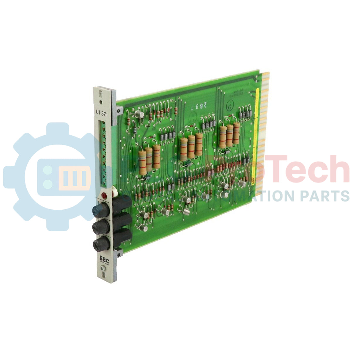
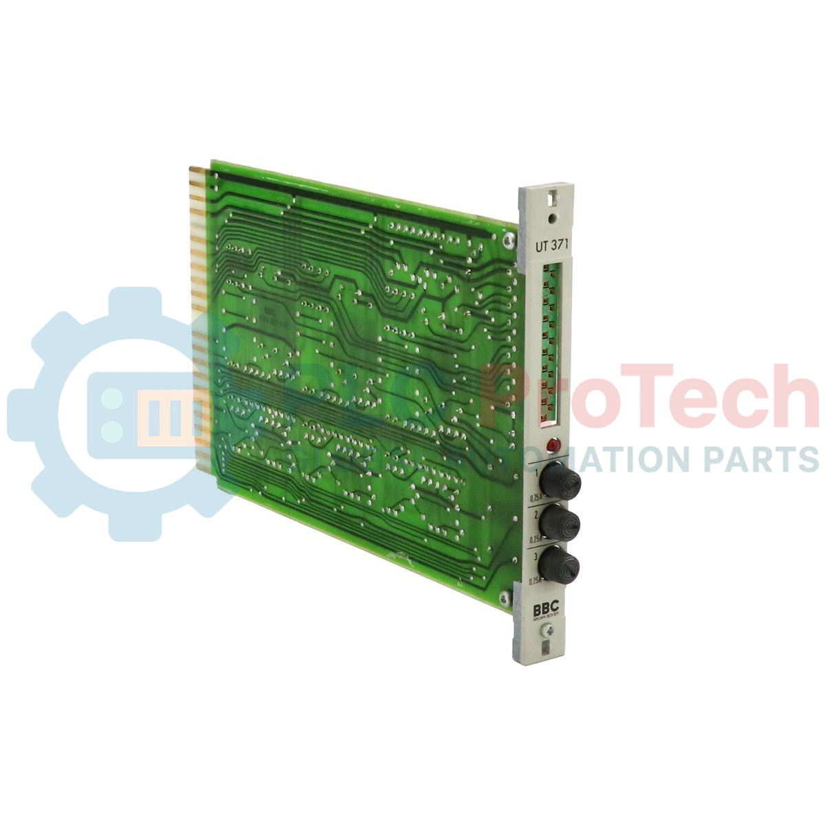
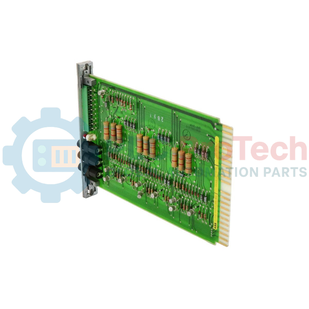
Description
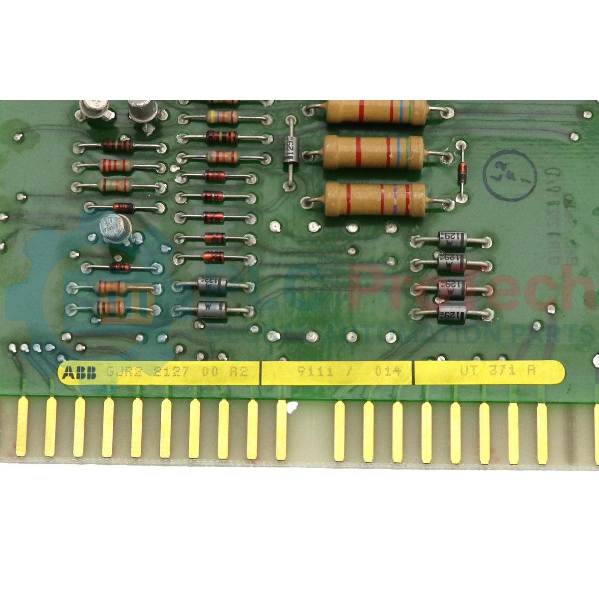
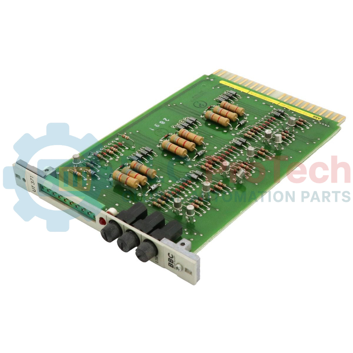
Designed to integrate seamlessly into the legacy Procontrol P13 turbine control architecture, the ABB UT371A V2 GJR2212700R2 functions as a dedicated diagnostic and communication interrogation interface. This unit polls local bus modules, retrieves live diagnostic status reports, and passes critical hardware integrity details back to the central processing units, ensuring real-time operational safety and system supervision.
Key Features
- Engineered specifically for the proprietary ABB Procontrol P13 bus communication protocol.
- Facilitates direct module diagnostics and status interrogation functions.
- Highly robust physical architecture optimized for demanding utility and power-generation environments.
- Low-heat profile design helps maintain stable enclosure temperatures within control racks.
Applications
- Steam and gas turbine control systems leveraging the Procontrol P13 platform.
- Thermal, nuclear, and hydroelectric power generation facilities.
- Heavy industrial utility installations requiring legacy bus network diagnostics.
Technical Specifications
| Parameter |
Specification |
| Manufacturer |
ABB |
| Model Designation |
UT371A V2 |
| Article Number (SKU) |
GJR2212700R2 (GJR2-212700-R2) |
| Control Series |
Procontrol P13 |
| Product Type |
Interrogation Module |
| Commodity Code |
85371091 |
| Shipping Weight (Calculated) |
0.36 kg (0.79 lbs) |
Engineering Notes & System Compatibility
Backward Revision Support: The UT371A V2 (GJR2212700R2) variant directly replaces legacy UT371 models. Prior to mounting, engineers must verify that all localized jumpers and station identification DIP switches are set identically to the failed module configuration to maintain address alignment across the local P13 bus.
Thermal Considerations: Enclosed legacy racks are prone to hot spots. Ensure proper cabinet ventilation and operational spacing around the sub-rack to prolong the life of the driver components on the card.
Diagnostic Verification: After insertion, system technicians must monitor the master diagnostics terminal. If the interrogation module fails to poll, verify physical backplane connection integrity and correct slot positioning, as offset cards can initiate bus communication faults.
Installation Guidelines
CRITICAL WARNING: De-energize the local rack or verify that hot-swapping permissions match plant-specific operating procedures before inserting this card. Touching backplane contacts with active current risks card damage and transient signal spikes.
1
Power down the target sub-rack or establish safety overrides on diagnostic loops.
2
Align the hardware jumper and DIP switch addresses according to original schematics.
3
Gently slide the module along the chassis rails until the card backplane connectors seat securely.
4
Apply power, confirm boot LEDs illuminate correctly, and execute a diagnostic bus scan.