Présentation
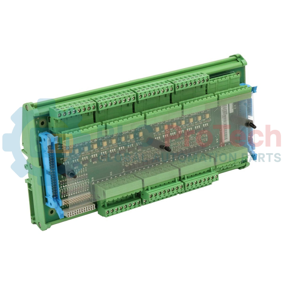
Le ABB Stromberg YPT-111A (également désigné sous le nom de YPT111A) est une carte terminale d’E/S étendue de qualité industrielle conçue pour servir d’interface principale de connexion des instruments de terrain dans l’architecture du système de contrôle Stromberg legacy. Fonctionnant en association avec la carte de traitement d’E/S étendue YPQ-111A , cette unité fait le lien entre les instruments numériques et analogiques de terrain et la logique de traitement centrale. Dans des installations de processus continus lourds telles que les usines de pâte et papier, les installations de traitement des métaux et les systèmes de distribution d’énergie marine, une défaillance de terminaison de signal peut bloquer des boucles de télémétrie critiques. Le YPT-111A résout ce problème en partitionnant les chemins de distribution d’alimentation et en organisant les signaux de terrain avant de les acheminer via deux connecteurs ruban plats 40 broches. Cette disposition isolée de l’interface simplifie considérablement l’accès au diagnostic, empêche les surtensions côté terrain de détruire l’électronique maître et contribue à réduire les temps d’arrêt système non planifiés.
Disposition du circuit et configuration de la topologie
La topologie du circuit du YPT-111A est centrée sur une architecture d’alimentation à double bus indépendante gérée via le connecteur d’alimentation principal X1. Pour minimiser l’injection de bruit et la propagation des défauts entre canaux, la carte maintient deux rails d’alimentation 24 VCC complètement séparés. Le premier rail, étiqueté +24V IN / BI, alimente spécifiquement les circuits d’entrée binaire via les broches 1, 3, 5 et 7 de X1. Le second rail, étiqueté +24V IN, alimente exclusivement la carte YPQ-111A associée lorsqu’elle est configurée comme nœud d’E/S série distant via les broches 9, 11, 13 et 15. La disposition matérielle comprend quatre positions de bornier en parallèle par rail, permettant aux techniciens de chaîner en série les boucles d’alimentation entrantes vers les cartes de terminaison YPT-111A ou YPT-111B adjacentes sans installer de blocs de distribution externes.
Matrice des paramètres matériels
| Paramètre |
Spécifications de performance |
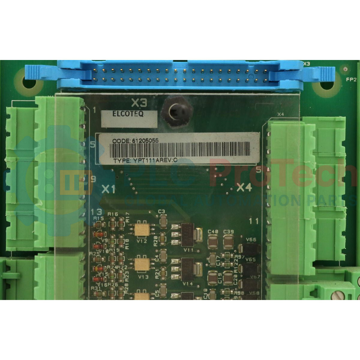
| Modèle |
YPT-111A (YPT111A) |
| Marque |
ABB Stromberg |
| Origine |
Finlande |
| Classe de composant |
Carte terminale d’E/S étendue |
| Module d’E/S compagnon |
YPQ-111A |
| Interconnexion de traitement |
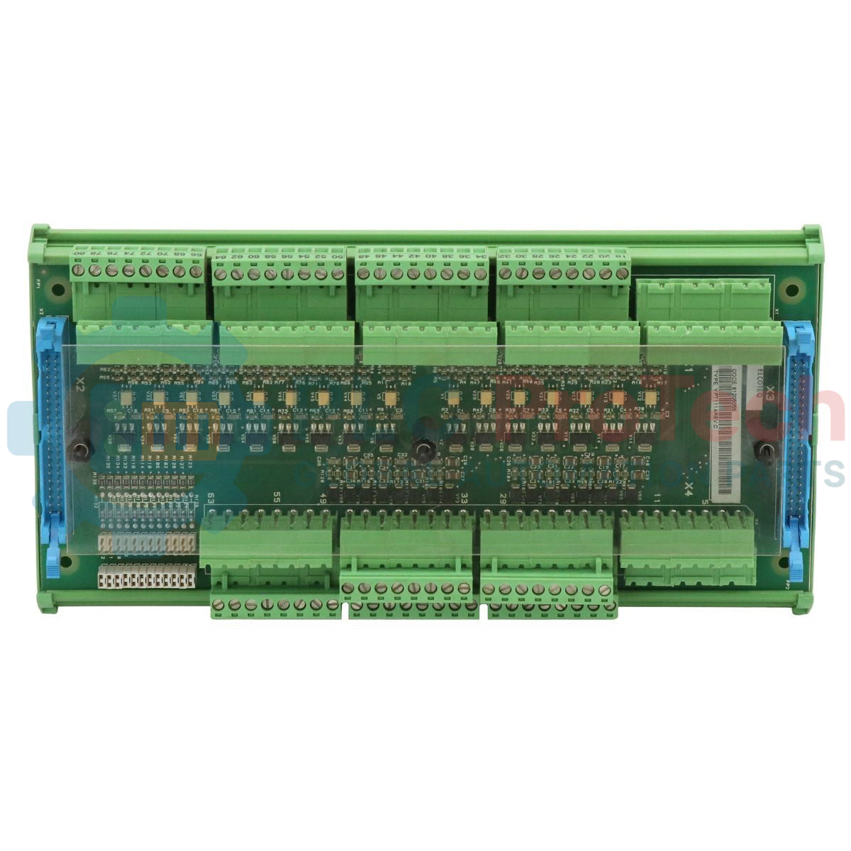
Interface double câble ruban plat 40 broches |
| Rails d’entrée de tension discrète |
2 entrées 24 VCC indépendantes |
| Bornes d’alimentation des entrées binaires |
Connecteur X1 : broches 1, 3, 5, 7 (+24V IN / BI) |
| Bornes d’alimentation du module distant |
Connecteur X1 : broches 9, 11, 13, 15 (+24V IN) |
| Capacité de chaînage des boucles |
4 points de passage internes par rail d’alimentation |
| Plateforme de contrôle maître |
Contrôleur d’application YPP-110A (via backplane local) |
| Plage de température de fonctionnement |
0 à 55 °C |
| Dimensions |
Format standard de terminaison pour rack/panneau Stromberg |
| Poids |
0,45 kg |
FAQ sur l’intégration système et la maintenance
Dans quelle condition système spécifique les broches 9, 11, 13 et 15 du connecteur X1 doivent-elles rester déconnectées ?
Les broches 9, 11, 13 et 15 du connecteur X1 ne doivent jamais être connectées ni alimentées en 24 VCC si la carte compagnon YPQ-111A fonctionne en mode E/S local. En configuration locale, la YPQ-111A tire son alimentation et sa logique directement du connecteur parallèle du backplane du contrôleur d’application YPP-110A au lieu d’utiliser l’option de bus série distant.
Comment fonctionne le mécanisme de chaînage d’alimentation entre plusieurs cartes de terminaison ?
La carte offre quatre connexions parallèles internes pour le rail d’entrée binaire et le rail d’alimentation d’E/S distant. Lors du chaînage des cartes, l’alimentation principale 24 VCC est introduite dans la première borne. Les trois broches restantes de ce bloc de bornes fonctionnent automatiquement comme sorties d’alimentation parallèles, permettant de relier directement l’alimentation 24 VCC au bloc suivant en série.
Quel type de câblage est nécessaire pour connecter la carte terminale au module d’E/S interne ?
L’interconnexion nécessite deux câbles ruban plats haute densité identiques de 40 broches. Ces câbles doivent être régulièrement inspectés pour détecter toute usure d’isolation ou fissure physique, surtout lorsqu’ils sont déployés dans des enceintes exposées à des vibrations industrielles basse fréquence.
Guide de mise en service sur site et câblage de sécurité
-
Insertion des câbles ruban : Coupez toute alimentation du système de contrôle avant de connecter les câbles ruban plats doubles 40 broches entre la carte YPT-111A et la carte YPQ-111A . Alignez les clés polaires des deux connecteurs ruban avec les emplacements correspondants sur la carte pour éviter de plier ou de désaligner les broches.
-
Séparation des bus d’alimentation : Vérifiez que l’alimentation des instruments de terrain 24 VCC (+24V IN / BI) et l’alimentation logique distante (+24V IN) proviennent de sources de bornier isolées si les spécifications d’isolation du système exigent une fusion de circuit séparée. Ne court-circuitez pas les bus d’alimentation distincts sur le connecteur X1 lors de la mise en service.
-
Limite de chaînage et sécurité contre les surintensités : Lors du chaînage des boucles 24 VCC vers des cartes secondaires YPT-111A ou YPT-111B , calculez la consommation cumulée de courant de toutes les boucles binaires actives. Assurez-vous que la charge combinée ne dépasse pas la capacité en ampérage des pistes cuivre ou du fusible d’alimentation principal installé dans le panneau.
-
Dégagement du backplane local : Lorsque vous utilisez la carte YPQ-111A en E/S locale connectée directement au contrôleur d’application YPP-110A , assurez-vous qu’aucun câble ni cavalier ne touche les broches 9 à 15 du connecteur X1. Isolez ces positions de bornier pour éviter tout court-circuit accidentel lors de la maintenance courante du panneau.