Présentation du produit
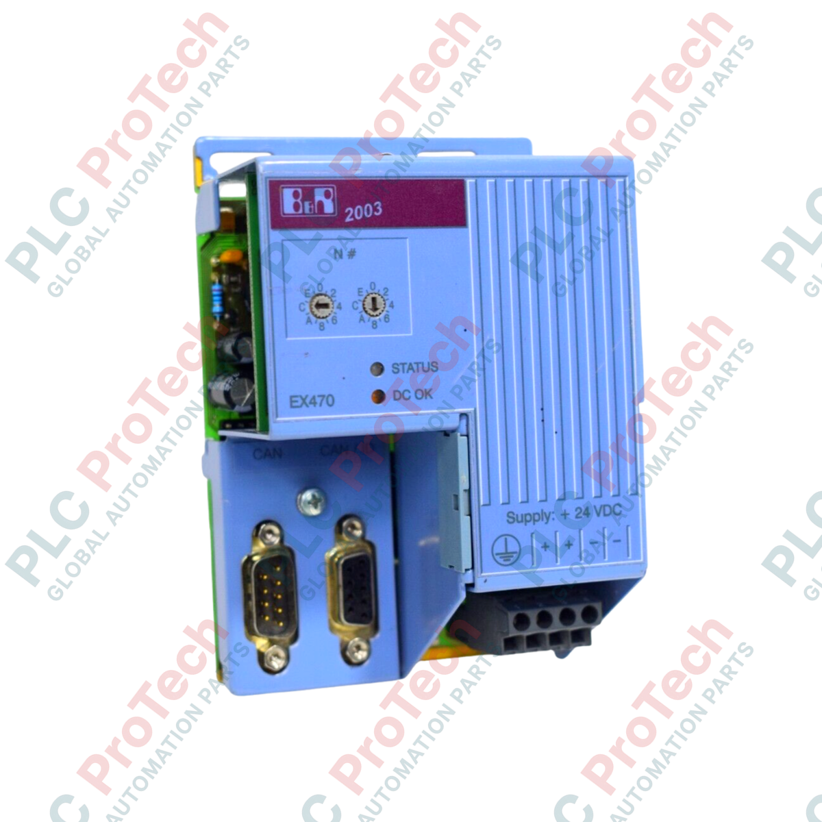
Le 7EX470.50-1 (7EX470.50-1) est un module contrôleur CAN bus compatible réseau, conçu pour l’architecture de contrôle industriel B&R 2003. Ce module joue un rôle clé de passerelle de communication, facilitant un échange de données fiable entre les systèmes d’E/S distribués et le contrôleur principal via deux interfaces CAN électriquement isolées. Sa conception privilégie la continuité opérationnelle dans des environnements à fort bruit, tels que les systèmes de manutention de matériaux à grande échelle, la logistique automatisée et les applications de contrôle de mouvement multi-axes, où une communication réseau robuste est essentielle pour éviter les arrêts système généralisés.
Configuration technique
Le 7EX470.50-1 est conçu pour une intégration réseau haute performance, avec deux interfaces CAN électriquement isolées afin d’éviter les boucles de masse. Le module permet une configuration précise des paramètres réseau, notamment l’identification du nœud et le débit en bauds, via un commutateur numérique intégré situé sur le panneau avant.
En termes de gestion de l’alimentation, le module fonctionne sur une alimentation standard 24 VDC (plage opérationnelle de 18 VDC à 30 VDC). Au-delà de sa propre consommation électrique (max. 20 W), il agit comme un nœud de distribution d’énergie, fournissant 14,5 W de puissance de sortie pour alimenter les modules d’E/S et les modules à vis connectés. Cette distribution d’énergie intégrée simplifie le câblage dans l’armoire et garantit que les modules périphériques restent alimentés de manière constante dans le système rack 2003.
Caractéristiques techniques
| Caractéristique |
Spécification |
| Modèle |
7EX470.50-1 |
| Marque |
B&R |
| Série |
B&R 2003 |
| Type de module |
Contrôleur CAN Bus |
| Interfaces CAN |
2 (électriquement isolées) |
| Tension d’entrée |
18 à 30 VDC (Nominal 24 VDC) |
| Consommation électrique |
Max. 20 W |
| Puissance de sortie E/S |
14,5 W |
| Interface |
Connecteur D-sub 9 broches |
| Configuration |
Commutateur numérique intégré |
| Poids |
1,5 kg |
FAQ
Quel est le rôle du commutateur numérique sur le module ?
Le commutateur numérique est une interface physique utilisée pour régler manuellement l’adresse du nœud CAN et le débit en bauds du réseau, garantissant que le contrôleur soit correctement reconnu par le système maître lors de la mise en service.
Quels sont les avantages de l’isolation électrique pour le réseau CAN bus ?
L’isolation électrique protège les transceivers de communication du module contre les surtensions et les différences de potentiel de masse entre les différents nœuds du réseau, ce qui augmente considérablement la fiabilité du réseau et prévient les dommages aux ports.
Puis-je chaîner l’alimentation via ce module ?
Le 7EX470.50-1 fournit 14,5 W de puissance de sortie aux modules d’E/S adjacents dans le même rack. Veillez à ce que la demande totale en puissance de vos modules connectés ne dépasse pas cette valeur.
Que se passe-t-il si la tension d’entrée descend en dessous de 18 VDC ?
Le module est spécifié pour fonctionner entre 18 et 30 VDC. En dessous de ce seuil, la communication peut devenir instable, la synchronisation réseau peut être perdue, ou le module peut se réinitialiser.
Installation et bonnes pratiques réseau
-
Terminaison CAN : Assurez-vous que les deux extrémités physiques du réseau CAN bus soient terminées par une résistance de 120 ohms. Une terminaison incorrecte provoque souvent des réflexions de signal, se traduisant par des erreurs de communication intermittentes ou des états « bus off ».
-
Choix du câble : Utilisez des câbles torsadés blindés de haute qualité, spécialement conçus pour les applications CAN bus. Évitez de faire passer les câbles de communication parallèlement aux lignes haute tension ou aux câbles d’alimentation des moteurs pour réduire les interférences électromagnétiques.
-
Protocole de mise à la terre : Maintenez un schéma de mise à la terre cohérent sur l’ensemble du réseau. Bien que les interfaces du module soient isolées, la tresse de blindage du câble doit être reliée à une terre fonctionnelle propre en un point central pour assurer une dissipation efficace des bruits.
-
Correspondance du débit en bauds : Tous les nœuds du réseau CAN doivent être configurés avec le même débit en bauds. Utilisez les commutateurs numériques intégrés avec précaution ; un décalage de débit empêchera le module d’entrer dans le réseau et peut provoquer des trames d’erreur sur le bus.