Description
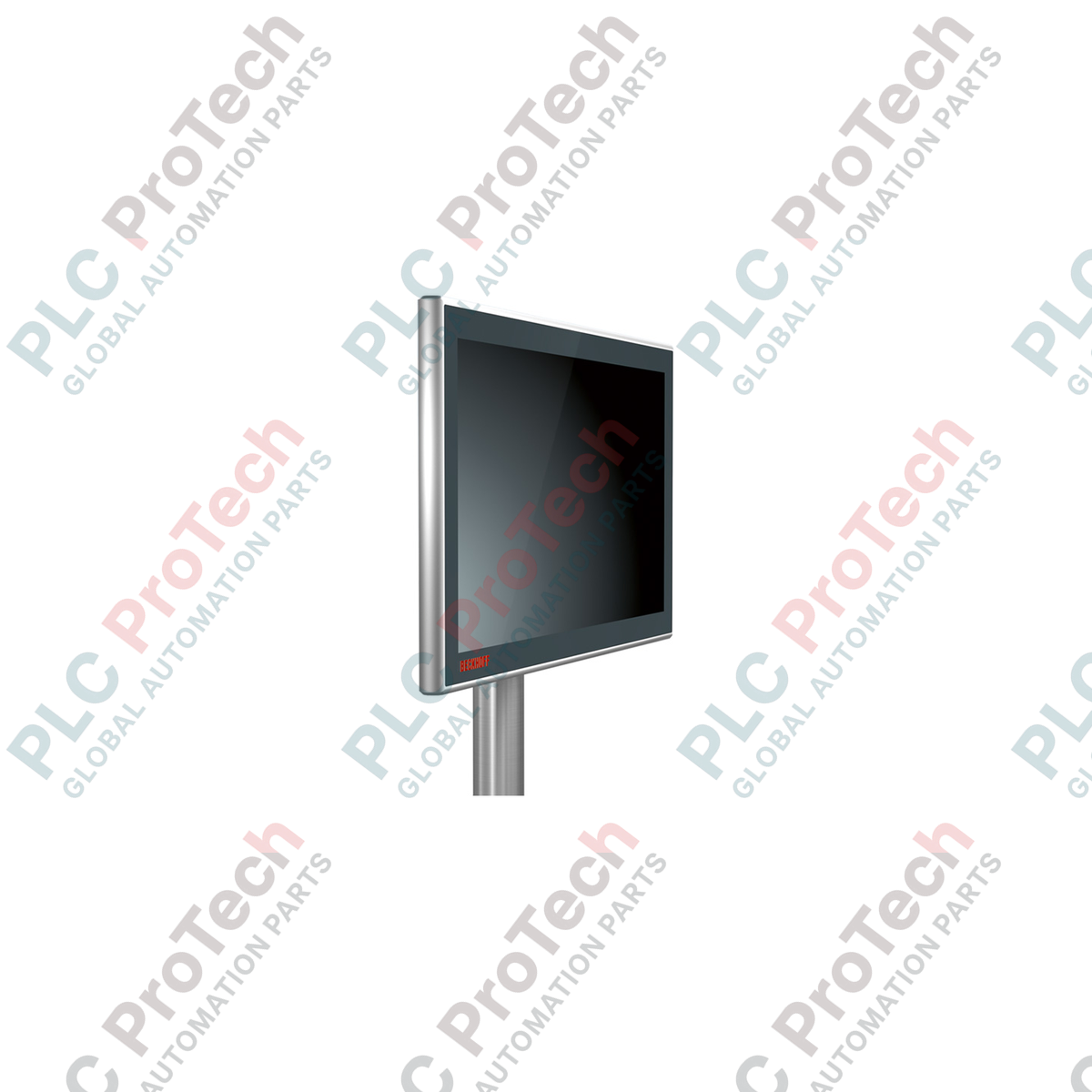
Serving as a highly resilient human-machine interface for distributed control topologies, the Beckhoff CP3915-0010 brings industrial-grade visualization directly to the field level. This premium control panel combines a robust 15-inch display with capacitive multi-finger touch technology, enclosed within an all-round IP65-rated aluminum housing with a high-durability glass front. Engineered to run seamlessly with the proprietary CP-Link 4 transmission standard, the unit consolidates video signals, USB 2.0 control signals, and power distribution into a single high-speed network infrastructure, enabling clean installations across extended distances without signal degradation.
Key Features
-
High-Fidelity Display: 15-inch screen operating at a native resolution of 1024 x 768 pixels for clear process visualization.
-
Multi-Touch Technology: Projected capacitive touch (PCT) sensor allows multi-finger input tracking, enabling gesture control and dual-hand safety confirmations.
-
CP-Link 4 Integration: Utilizes One Cable Technology (OCT) to transmit DVI, USB 2.0 (100 Mbit/s), and supply power up to 100 meters over a single Cat.6A cable.
-
Rugged Environmental Protection: Complete IP65 protection rating provides total dust ingress prevention and resistance to low-pressure water jets from all angles.
-
Sturdy Industrial Housing: CNC-milled aluminum housing with a chemically hardened glass front resistant to scratching and chemical exposure.
Applications
-
Automotive Assembly Lines: Mounting directly onto articulating arms next to robot cells for intuitive localized cell operations.
-
Food & Beverage Processing: Rugged design stands up to standard washdown protocols and localized humidity variations.
-
Material Handling & Logistics: Clean overhead installation via standard mounting arms provides reliable status feedback across large sorting hubs.
Technical Specifications
| Manufacturer |
Beckhoff Automation |
| Model Reference |
CP3915-0010 |
| Display Size |
15-inch |
| Resolution |
1024 x 768 pixels |
| Touch Technology |
Multi-finger touch (Projected Capacitive) |
| Interface Type |
CP-Link 4 (via standard Cat.6A cables) |
| Connector Ports |
2 x M12 round connectors (IP65-rated) |
| Protection Class |
IP65 (all-round) |
| Operating Temperature |
0 to 50 degC (ambient storage limit: -20 to 60 degC) |
| Mounting Configuration |
4 x M6 threaded holes at 100 x 100 mm pitch on connection block |
| Country of Origin |
Germany |
| Shipping Weight (Calculated) |
6.0 kg |
Connections & Interfaces
| Connector Port |
Signal / Power Assignment |
| M12 Connector (Port 1) |
CP-Link 4 connection (transmits USB 2.0, DVI, and OCT Power) |
| M12 Connector (Port 2) |
Optional external 24 VDC power supply connection (used when transmitter operates in dual-cable configuration) |
Empirical Engineering Insights
Alternative Models & Compatibility
Unlike legacy CP-Link 3 architectures which required dedicated PCIe cards in the Industrial PC, the CP39xx series relies on external transmitter modules (such as the CU8802 or CU8803). Ensure that your upstream host PC has a verified compatible transmitter interface. Attempting to drive this panel directly via generic standard USB or display adapters over passive extensions will result in a failure of both the display engine and touch feedback.
Application Pitfalls & Engineering Notes
In deployments with severe electromagnetic interference (EMI), such as those located near heavy robotic welding cells or variable frequency drives (VFDs), any interruption in the Cat.6A shielding path can trigger USB dropouts or screen flickering. Always verify end-to-end ground continuity on the external shielding. Do not route the CP-Link 4 cable parallel to high-voltage power conduits without a grounded metal divider barrier.
Commissioning & Wiring Tips
When operating this control panel via the One Cable Technology (OCT) option, the host transmitter injects 24 VDC directly into the Cat.6A loop. Ensure that the total cable run does not exceed 100 meters, as copper losses on substandard cables can cause the supply voltage to sag below the operational 19.2 VDC lower threshold, leading to unpredictable device resets during thermal cycling.
Installation Guidelines
CRITICAL WARNING: Verify that the host transmitter module and all primary supply lines are fully de-energized before connecting or disconnecting the M12 round connectors. Hot-plugging CP-Link 4 interfaces during active OCT power distribution can cause internal arc-damage to high-pin-density connectors, leading to permanent transceiver degradation.
1
Mount the hardware onto your mechanical support bracket or articulating swing-arm system using four M6 bolts tightened into the connection block at a standard 100 x 100 mm orientation. Maintain the recommended tightening torque specified by the arm manufacturer.
2
Run a continuously shielded Cat.6A Ethernet line (with rugged, industrial-grade RJ45 or M12 terminations) from the transmitter block inside the control cabinet directly to the control panel's CP-Link 4 interface.
3
Secure all M12 threaded couplings tightly to ensure moisture-tight sealing. Once mechanical locks are checked, apply primary power to the host system and verify proper operating OS touch calibration.