Description
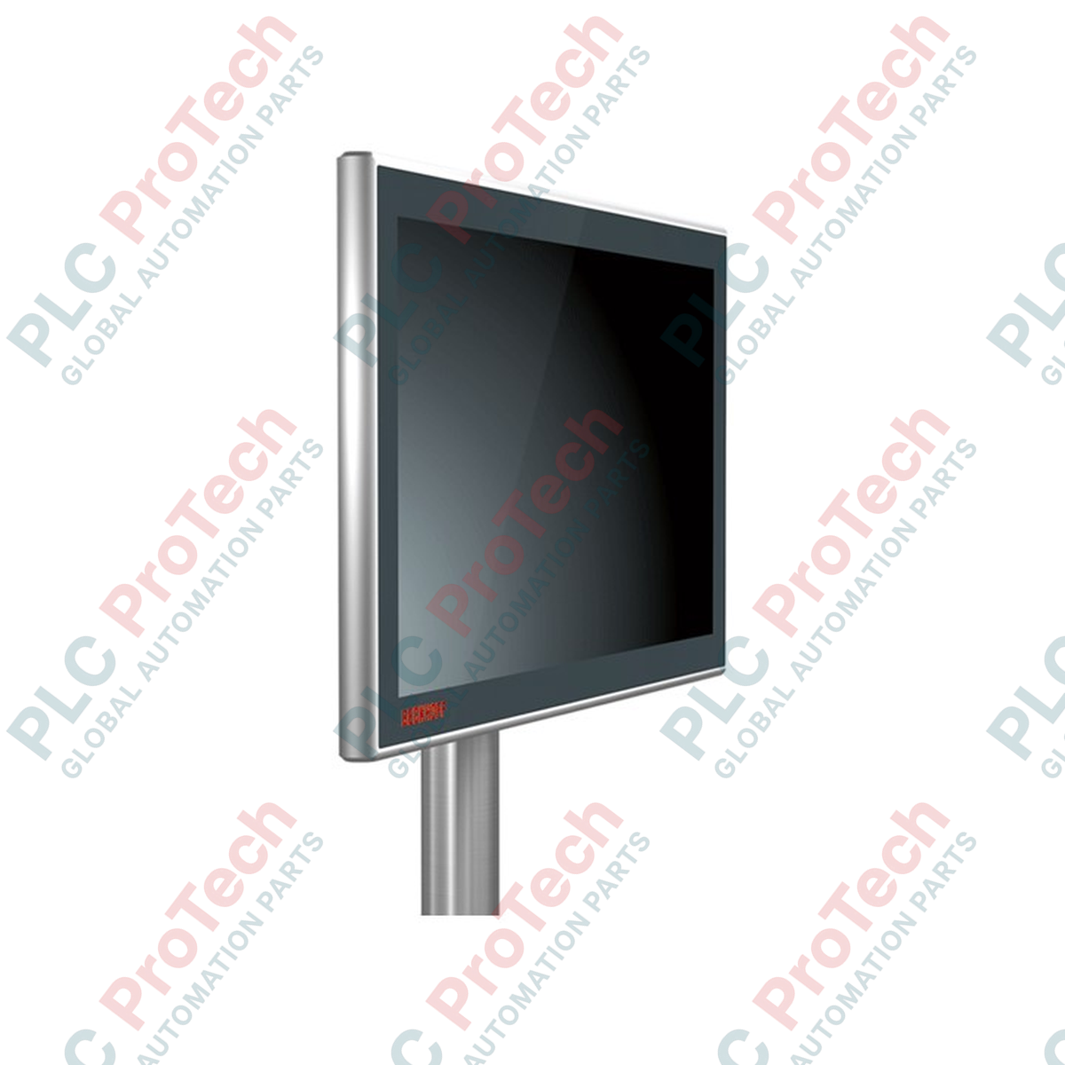
Designed for high-performance visualization directly at the machine level, the Beckhoff CP3918-0000 integrates a widescreen 18.5-inch display with robust multi-touch interface technologies. Operating as an industrial-grade display terminal, this unit utilizes DVI-E and USB-E 2.0 transmission standards, enabling reliable remote operation at distances up to 50 meters from the industrial PC (IPC). Wrapped in a high-protection all-round IP65 housing, this control panel withstands demanding physical environments while maintaining precise multi-finger capacitive input sensitivity.
Key Features
-
High-Resolution Display: 18.5-inch screen operating at 1366 x 768 widescreen resolution for detailed process graphics.
-
Extended Connectivity: Integrated DVI-E and USB-E 2.0 ports support clear signal and high-speed data transfer up to 50 meters without signal degradation.
-
Industrial Protection: Full IP65 sealing, featuring an aluminum housing with a robust glass front to protect against moisture, dust, and particulate contamination.
-
Multi-touch Interface: Projected capacitive touch (PCT) sensor technology supports multi-finger tracking and complex gesture control.
-
Flexible Mounting: Equipped with a standard mounting arm adapter compatible with 48 mm tube mounting systems.
Applications
-
Distributed IPC Topologies: Ideal for setups where the control cabinet PC is located remotely to protect core hardware from physical shop floor hazards.
-
Heavy Machinery Automation: Direct deployment on robotic cells, automotive assembly lines, and milling machines.
-
Hygienic Process Controls: Suitable for modern packaging and pharmaceutical lines requiring clean, wipeable glass fronts with zero crevices.
Technical Specifications
| Specification Parameter |
Technical Rating / Value |
| Manufacturer |
Beckhoff Automation |
| Model Reference |
CP3918-0000 |
| Display Size & Aspect Ratio |
18.5-inch (16:9 widescreen) |
| Resolution |
1366 x 768 pixels |
| Touch Technology |
Projected Capacitive Touch (PCT) Multi-touch |
| Interface Standard |
DVI-E and USB-E 2.0 |
| Maximum Cable Length |
50 meters |
| Operating Voltage |
24 V DC (minus 15 percent / plus 20 percent) |
| Protection Class |
IP65 (all-round) |
| Operating Temperature |
0 to 55 Celsius |
| Housing Construction |
Aluminum housing with laminated safety glass front panel |
| Mounting Connection |
4 x M6 threaded holes (100 x 100 mm pitch) / 48 mm tube adapter |
| Shipping Weight (Calculated) |
5.0 kg (11.0 lbs) |
Connections and Interfaces
| Port / Connection Terminal |
Signal / Interface Description |
| 24 V DC Power Supply Input |
3-pin connection (+24 V, 0 V, Functional Earth) |
| DVI-E Connector |
Industrial DVI-D input from PC transmitter over extended line |
| USB-E 2.0 Connector |
Industrial USB-E 2.0 type B connector for touch and peripheral return |
| External USB Ports |
IP65-rated USB ports for connecting external flash drives/peripherals |
Empirical Engineering Insights
Alternative Models & Compatibility
The CP3918-0000 control panel operates strictly as a display and touch terminal without an integrated CPU or operating system. Host integration requires a specialized transmitter unit on the PC side, such as the CU8801 (USB-E-2.0 extender) or equivalent Beckhoff PCIe module cards. If your machine architecture features a localized computer, consider upgrading to the CP2918 series, which features built-in single-touch or multi-touch motherboard options.
Application Pitfalls & Engineering Notes
When laying extended DVI-E and USB-E cables up to the 50-meter threshold, you must prevent tight bending loops inside the cable carrier tracks. Signal attenuation and jitter issues can disrupt the PCT touch tracking matrix if high-flex dynamic cables are used past their rated fatigue limit. Furthermore, avoid cascading external USB hubs at the display terminal end, as this may exceed USB timing margins over the extended 50-meter line.
Commissioning & Wiring Tips
To prevent "ghost touches" or erratic mouse behavior induced by variable speed drives (VSDs) and other high-frequency noise sources on the machine frame, ensure the mounting arm adapter has a direct, low-impedance copper ground connection to the main system ground. Use shielded, factory-terminated Beckhoff DVI-E/USB-E hybrid cables to maintain signal integrity.
Installation Guidelines
CRITICAL WARNING: De-energize all primary and auxiliary 24 V DC power sources before connecting or disconnecting the DVI-E, USB-E, or power cables. Hot-plugging industrial display data lines while the circuit is live can cause transient ground loop current spikes that can permanently damage the sensitive internal controller boards.
1
Mount the control panel onto the 48 mm tube adapter structure. Verify the 4 M6 threaded bolts are tightened to the specified torque setting of 4.5 Nm.
2
Connect the functional earth line directly from the mounting block terminal to the machine ground reference bus.
3
Route the DVI-E and USB-E cables through the center of the mounting tube, avoiding tight bends, and lock the IP65 circular connectors securely into their designated ports.
4
Connect the 3-pin 24 V DC power supply plug, verifying voltage polarity before energizing the electrical circuit.