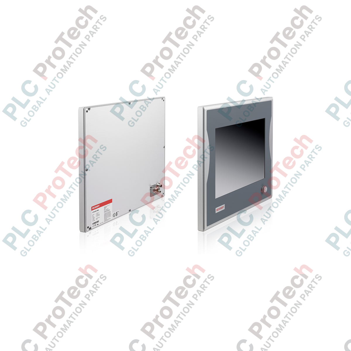
Description
Designed to bridge the gap between industrial computing and clean operator visualization, the Beckhoff CP7921-0000-0000 delivers robust interface capabilities directly to the field level. This space-saving industrial control panel features a high-visibility 12-inch TFT display with an 800 x 600 resolution, packaged inside a rugged aluminum housing. Operating as a remote visual terminal, the panel utilizes integrated DVI-E and USB-E 2.0 connection technology to transmit uncompressed video and high-speed USB signals from a control cabinet PC across distances of up to 50 meters. Complete IP65 protection ensures complete resilience in demanding industrial environments where exposure to dust, moisture, and mild washdowns is common.
Key Features
-
High-Resolution Display: 12-inch active matrix TFT screen with 800 x 600 SVGA resolution for crisp industrial graphics and diagnostics.
-
DVI-E and USB-E 2.0 Interface: Enables lossless video transfer and 480 Mbit/s USB 2.0 communication over long-distance cable lengths up to 50 m.
-
All-Weather IP65 Protection: Fully sealed aluminum housing with IP65-rated connections, safeguarding internal electronics from liquids and airborne contaminants.
-
Robust Mechanical Design: Rear-side mounting layout with four M6 threaded holes designed for direct integration with support arm adapters.
-
Industrial Supply Standard: Runs on a standard 24 V DC input, accommodating typical control cabinet power environments.
Applications
- Automotive assembly lines utilizing remote host industrial PCs.
- Food and beverage packaging plants requiring IP65 washdown-rated operator panels.
- Heavy machinery control stations with swing-arm terminal setups.
- Pharmaceutical cleanrooms requiring chemically resistant aluminum bezels.
Technical Specifications
| Manufacturer |
Beckhoff |
| Model Code |
CP7921-0000-0000 |
| Device Classification |
Economy Control Panel |
| Display Size |
12-inch |
| Resolution |
800 x 600 pixels (SVGA) |
| Housing Material |
Milled aluminum |
| Protection Class |
IP65 (all directions) |
| Connection Technology |
DVI-E and USB-E 2.0 |
| Maximum Cable Length |
Up to 50 meters |
| Interfaces |
DVI, USB-E 2.0 (IP65-rated connectors) |
| Supply Voltage |
24 V DC |
| Operating Temperature |
0 to 55 degC |
| Mounting Mechanism |
4 x threaded holes (M6 x 18 mm) in backplane |
| Country of Origin |
Germany |
| Shipping Weight (Calculated) |
8.0 kg |
Connections and Interfaces
| Port / Connector |
Function / Circuit Assignment |
| DVI-E Input |
Connects to standard DVI output of a host industrial PC via shielded DVI-E cable (IP65 sealed). |
| USB-E 2.0 Port |
Transmits high-speed USB 2.0 peripheral signals (up to 480 Mbit/s) back to the main PC. |
| Power Terminal |
3-pin connection for 24 V DC power supply input. |
Empirical Engineering Insights
Alternative Models & Compatibility: The CP7921-0000-0000 serves as a plug-and-play field terminal compatible with any Beckhoff Industrial PC (such as the C69xx or C66xx series) that provides standard DVI and USB interfaces. Because it relies on standard USB-E and DVI-E rather than proprietary CP-Link 4 transmitter cards, physical system migrations do not require internal PC upgrades.
Application Pitfalls & Engineering Notes: Signal degradation on DVI-E and USB-E 2.0 connections can occur if cables are run inside high-noise wireways alongside VFD motor lines. Ensure a physical separation of at least 100 mm from high-voltage cables. Avoid exceeding the 50-meter direct cable specification, as latency and frame dropping can occur on the visual feed.
Commissioning & Wiring Tips: To prevent voltage drops across long runs, run a dedicated, thick-gauge 24 V DC supply cable directly to the panel. Do not daisy-chain the 24 V DC supply with high-draw solenoid blocks or inductive switching components to protect the panel from inductive voltage spikes.
Installation Guidelines
CRITICAL WARNING
Isolate and lock out all 24 V DC field electrical circuits before attempting mechanical installation or cabling. Hot-plugging the DVI-E or USB-E 2.0 cables can cause electrostatic discharge (ESD) events, permanently damaging the receiver electronics inside the panel.
1
Mount the enclosure to the supporting arm adapter using four M6 bolts. Insert the bolts into the rear-panel threaded holes to a maximum depth of 18 mm.
2
Establish a solid functional ground connection from the aluminum housing ground terminal directly to the machine ground point using low-impedance copper strap.
3
Route the shielded DVI-E and USB-E 2.0 connection cables into the designated port slots and tighten the threaded IP65 collars to maintain environmental sealing.
4
Terminate the 24 V DC supply cables on the power plug, verifying correct polarity, then insert the plug into the socket and secure the holding screws.