Description
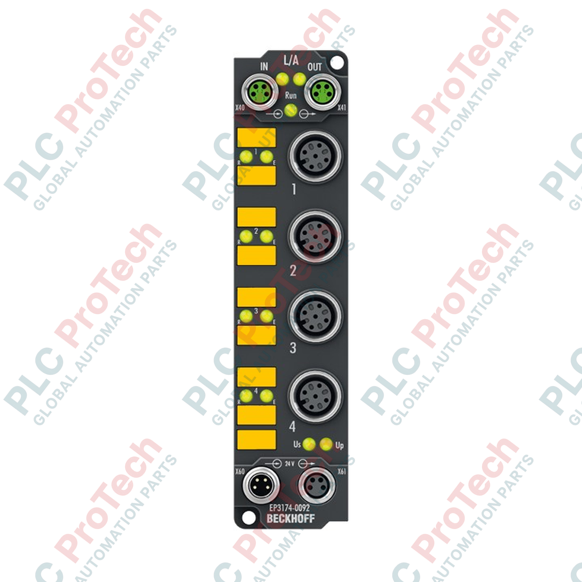
Engineered for direct field installation without an electrical enclosure, the Beckhoff EP3174-0092 EtherCAT Box provides four high-precision, individually parameterizable differential analog inputs. This IP67-rated module processes signals in the ranges of -10/0 to +10 V or 0/4 to 20 mA per channel, offering 16-bit resolution with integrated Distributed Clocks for precise temporal synchronization. Its robust, fully-sealed design makes it ideal for harsh industrial environments where decentralized signal acquisition is required.
Key Features
-
Four Differential Inputs: Individually parameterizable for voltage or current signals.
-
16-Bit Resolution: High-precision digitization (including sign) for demanding measurement tasks.
-
High-Speed Processing: 100 us conversion time with a 5 kHz input filter limit frequency.
-
Distributed Clocks: Supports ultra-precise, synchronized time-stamped data acquisition across the EtherCAT network.
-
Rugged Build: IP65/66/67 protection rating for moisture, dust, and washdown protection.
-
Standardized Connectors: M12 x 1 analog interface combined with M8 EtherCAT and power interfaces.
Applications
- Decentralized process measurement in machine building and plant engineering.
- Heavy-duty automated material handling and conveyor installations.
- On-machine mounting in wet or high-vibration manufacturing environments.
- Distributed sensor integration requiring rapid loop update times.
Technical Specifications
| Manufacturer |
Beckhoff Automation GmbH & Co. KG |
| Model Number |
EP3174-0092 |
| Protocol |
EtherCAT |
| Number of Inputs |
4 (Differential) |
| Signal Types |
-10/0...+10 V | 0/4...20 mA (Configurable per channel) |
| Resolution |
16-bit (including sign) |
| Conversion Time |
approx. 100 us |
| Internal Resistance |
> 200 kOhm (Voltage) | typ. 85 Ohm + diode voltage (Current) |
| Common-Mode Voltage (U_CM) |
max. 35 V |
| Measurement Error |
< +/-0.3% (relative to full scale value) |
| Nominal Supply Voltage |
24 V DC (-15% / +20%) |
| Current Consumption (from U_S) |
120 mA |
| Electrical Isolation |
500 V |
| Operating Temperature |
-25 to +60 degC |
| Storage Temperature |
-40 to +85 degC |
| Protection Rating |
IP65/66/67 (conforms to EN 60529) |
| Approvals |
CE, UL |
| Country of Origin |
Germany |
| Shipping Weight (Calculated) |
0.5 kg (Net Unit Weight: 165 g) |
| Package Dimensions (Calculated) |
150 x 40 x 40 mm |
Connections and Interfaces
| Connector / Port |
Interface & Pin Assignment |
| Input Channels (1 to 4) |
M12 x 1 female socket, 5-pin, A-coded (Pin 1: +24V Sensor supply; Pin 2: Input +; Pin 3: GND; Pin 4: Input -; Pin 5: Shield) |
| EtherCAT Bus |
2 x M8 socket, 4-pin, shielded, screw type (Input and downstream Connection) |
| Power Supply Feed |
1 x M8 male socket, 4-pin (Pin 1: +24V US; Pin 2: +24V UP; Pin 3: GND S; Pin 4: GND P) |
| Power Downstream |
1 x M8 female socket, 4-pin (For daisy-chaining supply to next node) |
Empirical Engineering Insights
Alternative Models & Compatibility
The EP3174-0092 utilizes standard EtherCAT XML Device Description (ESI) files. In older TwinCAT 2.11 environments, make sure to update the device description repository to correctly resolve the -0092 hardware profile. It acts as a drop-in physical replacement for older IP67 analog input modules, provided the pin assignments for the differential ground connections are respected.
Application Pitfalls & Engineering Notes
When using differential inputs, ensure that the common-mode voltage between any input signal and the module's internal ground does not exceed the maximum rating of 35 V DC. If you are integrating 3-wire sensors or ungrounded signal generators, a high impedance path to the system ground should be provided to prevent signal drift and potential saturation of the differential input stages.
Commissioning & Wiring Tips
Always configure the channel parameter settings (CoE Index 0x8000 to 0x8030) inside the TwinCAT System Manager prior to applying analog loops. Connecting an active 4-20 mA current loop while the channel is still configured for a 10V input range can lead to faulty process readouts, though the internal input stage is electrically protected from nominal overcurrent.
Installation Guidelines
CRITICAL WARNING:
Do not connect or disconnect any M8 or M12 connectors under active electrical load. Always isolate the 24V DC control supply (US) and the load supply (UP) before performing installation, maintenance, or reconfiguration. Failure to do so can cause permanent damage to the contacts and internal communication chipsets.
1
Mount the EP3174-0092 directly onto a flat machine surface or profile rail using two M3 screws through the integrated mounting ears.
2
Ensure the physical earthing path is secure by utilizing a conductive mounting surface or running a separate ground strap to the designated functional earth terminal.
3
Connect the shielded M12 analog input lines, verifying that the cable shields are correctly terminated to the connector sleeves.
4
Attach the M8 EtherCAT communication lines, secure with nominal screw-torque to ensure IP67 sealing, and apply power.