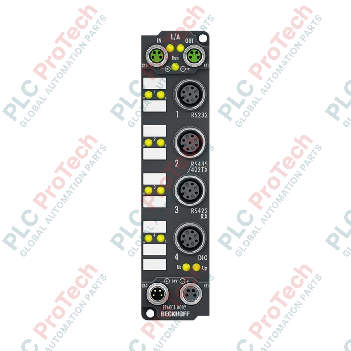
Description
Direct connection of serial devices to the EtherCAT network is achieved through the Beckhoff EP6001-0002 interface module, enabling local protocol translation and data buffering on the machine floor. This IP67-rated EtherCAT Box provides a single-channel, field-selectable interface supporting RS232, RS422, or RS485 communication protocols. Designed for demanding environments, it eliminates the need for protective enclosures, mounting directly onto machinery to connect serial barcode scanners, scales, readers, and legacy sensors. The module also features two built-in auxiliary digital I/O channels that can be individually configured as inputs or outputs, optimizing local signal routing and sensor integration.
Features
-
Selectable Serial Standards: Single-channel interface configurable for RS232, RS422, or RS485 operating modes.
-
Integrated Digital I/O: Two auxiliary channels configurable as digital inputs or digital outputs to support local sensor/actuator connections.
-
Industrial Protection: IP65, IP66, and IP67 sealing ratings allow for direct machine-mount installation without control cabinets.
-
Onboard Buffering: Equipped with an 864-byte receive buffer and a 128-byte transmit buffer to prevent data loss during high-rate transfers.
-
Flexible Baud Rates: Supports transmission speeds ranging from 300 to 115,200 baud, with 9600 baud preset as default.
-
Rugged M8/M12 Connectivity: Employs shielded M8 screw-type connectors for EtherCAT and M12 A-coded connectors for serial devices.
Applications
- Field-level integration of serial barcode readers, RFID scanners, and operator terminals.
- Direct connection of digital weighing systems and precision balance scales in wet or dusty processing environments.
- Interfacing legacy CNC or motion controller serial ports to modern EtherCAT architectures.
- Distributed machinery installations requiring localized sensor signal aggregation alongside serial telemetry.
Technical Specifications
| Parameter |
Value |
| Manufacturer |
Beckhoff |
| Model Number |
EP6001-0002 |
| Fieldbus Protocol |
EtherCAT |
| Bus Interface |
2 x M8 socket, shielded, screw-type |
| Serial Channels |
1 (individually selectable RS232, RS485, or RS422) |
| Data Transfer Rates |
300 to 115,200 baud (9600 baud preset; 8-bit, no parity, 1 stop bit) |
| Communication Mode |
TxD and RxD, full duplex |
| Bit Distortion |
< 3% |
| Maximum Cable Length |
RS232: 15 m; RS422/RS485: 1000 m |
| Data Buffers |
864 bytes (receive buffer), 128 bytes (transmit buffer) |
| Sensor Supply Voltage/Current |
+5 V DC, 1 A |
| Serial Connection Method |
M12 x 1, 5-pin, A-coded |
| Digital Auxiliary Channels |
2 (individually configurable as inputs or outputs) |
| Input Filter Time |
10 us (for digital inputs) |
| Digital Input Voltages |
"0" signal: -3 to +5 V; "1" signal: 11 to 30 V |
| Digital Input Current |
Typ. 3 mA (EN 61131-2, type 3) |
| Digital Output Type / Max Load |
Ohmic, inductive, lamp load; 0.5 A per channel (short-circuit proof) |
| Nominal System Voltage |
24 V DC (-15% / +20%) |
| Current Consumption (from Us) |
Typ. 130 mA + sensor supply load |
| Power Supply Connections |
Feed: 1 x M8 male, 4-pin; Downstream: 1 x M8 female, 4-pin |
| Electrical Isolation |
500 V RMS |
| Environmental Protection |
IP65, IP66, IP67 (conforms to EN 60529) |
| Operating / Storage Temp. |
-25 to +60 degC / -40 to +85 degC |
| Vibration / Shock Resistance |
Conforms to EN 60068-2-6 / EN 60068-2-27 |
| EMC Standards |
Conforms to EN 61000-6-2 / EN 61000-6-4 |
| Net Weight |
165 g |
| Shipping Weight |
2.0 kg |
| Approvals |
CE, UL |
Connections and Interfaces
| Connector / Interface Type |
Pin / Terminal Designation |
Function / Signal Assignment |
| EtherCAT Ports (M8, Female) |
Incoming M8 (In) |
EtherCAT network signal input |
| Downstream M8 (Out) |
EtherCAT network signal output to next node |
| Power Feed (M8, Male/Female) |
Pin 1 / Pin 3 |
+24 V DC control voltage (Us) / GNDs |
| Pin 2 / Pin 4 |
+24 V DC peripheral power (Up) / GNDp |
| Serial & I/O Port (M12, A-coded) |
Pins 1 to 5 |
RxD/TxD (RS232) or RxD/TxD +/- (RS485/422), Ground, and configurable digital I/O channels |
Empirical Engineering Insights
Alternative Models & Compatibility
The EP6001-0002 is functionally similar to the DIN-rail mounted KL6001 (Bus Terminal) and EL6001 (EtherCAT Terminal) components, but package-engineered for on-machine IP67 environments. Note that because physical pinout layouts differ between these product families, serial cabling must be terminated to match the specific pin map of the M12 interface used on the EP6001-0002. Ensure your EtherCAT master configuration (such as TwinCAT) is updated to include the appropriate XML device description (ESI) file specific to this IP67 box.
Application Pitfalls & Engineering Notes
When operating in RS232 mode, ensure serial cabling does not exceed the physical 15 m limit to prevent signal degradation and framing errors. For RS422 and RS485 systems spanning up to 1000 m, integrated line termination resistors should be configured in software to avoid signal reflections. In environments with heavy EMI (such as those containing variable frequency drives), always use shielded M8 and M12 cables connected directly to a low-impedance grounding block via the module's metallic ground tab.
Commissioning & Wiring Tips
Before powering up the system, confirm that the control voltage (Us) supply is adequately rated to handle both the base module current draw (130 mA) and the connected auxiliary sensor loads. Configuration of data transfer parameters (Baud rate, data bits, parity, stop bits) is performed entirely within the TwinCAT System Manager under the module's process data objects (PDOs). Ensure these software settings match the hardware configuration of the end device prior to executing read/write operations.
Installation Guidelines
CRITICAL WARNING: SAFETY COMPLIANCE FIRST
Always disconnect and isolate the 24 V DC auxiliary and system power sources (Us and Up) before inserting, removing, or wiring any EtherCAT or serial M12 connections. Physical manipulation of connections under electrical load can result in contact arcing, firmware corruption, or irreversible physical damage to the module's internal receiver electronics.
1
Mount the EP6001-0002 physically to a clean, flat surface on the machine frame using two M3 screws through the integrated mounting eyelets. Maximize electrical contact of the rear metallic grounding tab with the grounded machine surface.
2
Connect the incoming EtherCAT network cable to the M8 "IN" socket. Connect the downstream M8 "OUT" socket to consecutive EtherCAT boxes in the chain. Torque all M8 screw collars to manufacturer specifications to guarantee water-tight sealing.
3
Plug the serial and digital input/output device cables into the respective M12 female interfaces. Apply even torque to secure the M12 A-coded connectors and preserve the IP67 sealing rating.
4
Supply the +24 V DC system and auxiliary power. Perform online hardware scanning in TwinCAT to detect the new node, configure the required communication protocol via CoE registers, and begin fieldbus messaging.