Description
Acquiring field-level digital signals directly on machinery without protective enclosures is efficiently managed by the Beckhoff ER1008-0001, an IP67-rated EtherCAT Box designed for severe industrial environments. Encased in a robust, zinc die-cast housing, this module processes up to eight digital inputs from typical proximity sensors, switches, or photoelectric barriers. It integrates high-speed EtherCAT fieldbus communication via shielded M8 connectors, offering standard EN 61131-2 Type 1/3 input characteristics with a 3.0 ms input hardware filter for excellent noise suppression. The mechanical protection and direct-to-machine mounting capability eliminate the need for traditional terminal junction boxes, significantly reducing field installation overhead and cable routing complexity.
Features
-
Robust Die-Cast Construction: Zinc die-cast housing provides exceptional mechanical strength and resistance to harsh industrial environments.
-
High-Speed Communication: Direct EtherCAT interface via dual shielded M8 screw-type connection sockets.
-
Multi-Channel Processing: Eight independent digital input channels conforming to EN 61131-2 Type 1/3 specifications.
-
IP67 Environmental Seal: Fully protected against dust ingress and low-pressure water jets, enabling direct machine mounting.
-
Short-Circuit Protection: Integrated sensor power supply distributed directly from the control voltage, complete with short-circuit security up to 0.5 A.
-
Status Diagnostics: Bright optical LED diagnostics indicating local connection status and input channel activity.
Applications
-
Machine Tooling & Metal Cutting: Resistant to coolants, cutting fluids, and physical impacts.
-
Material Handling & Conveyors: Decentralized sensor integration over extended logistics systems without terminal cabinets.
-
Assembly & Robotics: Low weight and high vibration resistance make it suitable for installation on moving robotic arms or end-of-arm tooling.
-
Automotive Press Shops: Designed to withstand weld splatter and heavy vibration typical of automotive body assemblies.
Technical Specifications
| Parameter |
Specification Value |
| Manufacturer |
Beckhoff |
| Article Number (SKU) |
ER1008-0001 |
| Protocol |
EtherCAT |
| Number of Inputs |
8 |
| Input Specification |
EN 61131-2, type 1/3 |
| Input Filter Time |
3.0 ms |
| Nominal Input Voltage |
24 V DC (-15% / +20%) |
| "0" Signal Voltage |
-3 to +5 V (EN 61131-2, type 3) |
| "1" Signal Voltage |
11 to 30 V (EN 61131-2, type 3) |
| Input Current |
Typically 3 mA (EN 61131-2, type 3) |
| Sensor Supply |
From control voltage, max 0.5 A total (short-circuit proof) |
| Electrical Isolation |
Control voltage / fieldbus: Yes |
| Operating Temperature |
-25 to +60 degC |
| Storage Temperature |
-40 to +85 degC |
| Environmental Protection |
IP65 / IP66 / IP67 (conforms to EN 60529) |
| Housing Material |
Zinc die-cast |
| Vibration/Shock Resistance |
Conforms to EN 60068-2-6 / EN 60068-2-27 |
| EMC Immunity/Emission |
Conforms to EN 61000-6-2 / EN 61000-6-4 |
| Approvals/Markings |
CE, UL |
| Dimensions (W x H x D) |
30 mm x 126 mm x 26.5 mm |
| Weight |
approx. 265 g |
| Shipping Weight (Calculated) |
0.55 kg |
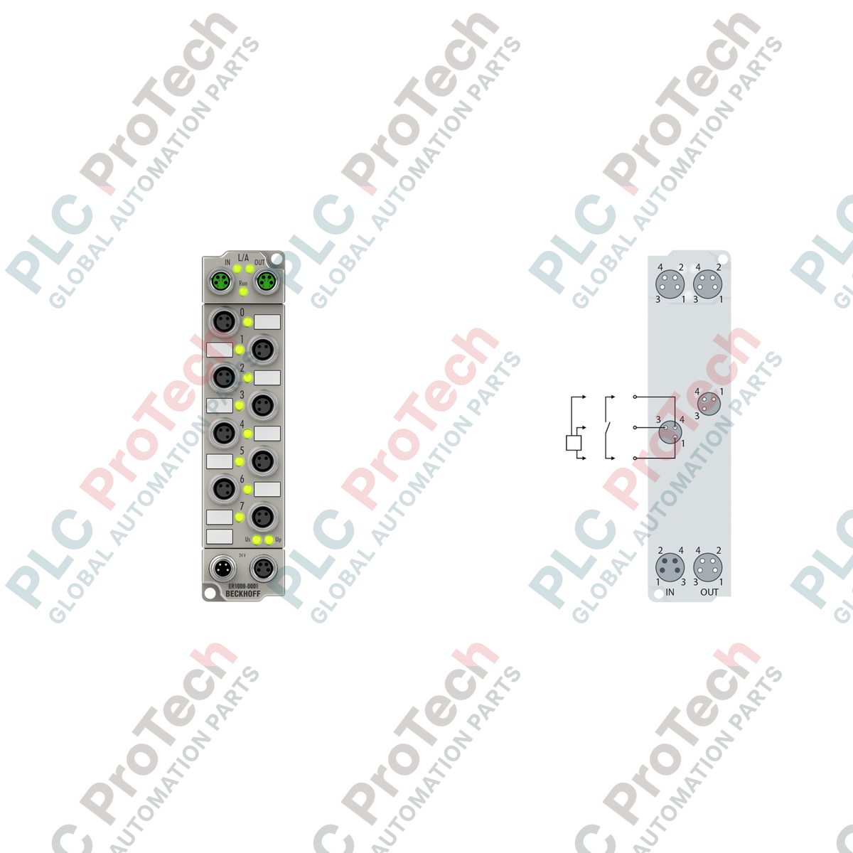
Connections and Interfaces
| Connection Interface |
Connector Type |
Assignment Description |
| EtherCAT Bus Interface |
2 x M8 socket (shielded, screw type) |
1 x Input, 1 x Output for EtherCAT daisy-chaining |
| Digital Inputs (Channels 1-8) |
8 x M8 (3-pin, a-coded, female) |
Pin 1: +24 V DC sensor supply, Pin 3: GND, Pin 4: Signal input |
| Power Feed Input |
1 x M8 (4-pin, male) |
Pin 1: +24 V DC Us (Control), Pin 2: +24 V DC Up (Auxiliary), Pin 3: GNDs, Pin 4: GNDp |
| Power Downstream Outlet |
1 x M8 (4-pin, female) |
Loop-through connection to downstream EtherCAT Box modules |
Empirical Engineering Insights
Alternative Models & Compatibility
The ER1008-0001 is functionally identical to the plastic-housed EP1008-0001. Both share the same twinCAT XML (ESI) configuration files, hardware process image layout, and electrical input curves. However, the ER series' zinc die-cast housing offers significantly superior shielding against electromagnetic coupling and physical endurance against hot metal weld slag. When upgrading an EP1008-0001 to an ER1008-0001, mounting dimensions are identical, enabling a direct physical swap without panel alterations.
Application Pitfalls & Engineering Notes
A common commissioning oversight is exceeding the 0.5 A total sensor supply current limit. The 24 V DC sensor supply distributed to Pin 1 across all 8 input channels is shared. If you are powering high-current draw devices (such as optical distance sensors or external valve indicators), keep in mind that a transient short circuit on a single channel will trip the sensor supply voltage for all 8 channels simultaneously. In high-density applications, calculate the aggregate sensor operating currents to ensure they remain below 0.5 A.
Commissioning & Wiring Tips
To guarantee continuous industrial communication speeds, ensure the M8 EtherCAT cabling is fully shielded and the connector shells are securely tightened. Because the EtherCAT bus operates at high frequencies, loose or unshielded connectors are susceptible to EMI-induced packet loss, causing temporary "SAFE-OP to OP" state transitions. Use Beckhoff pre-assembled ZB9020/ZS1090 series cables for optimal network stability.
Installation Guidelines
CRITICAL WARNING: SAFETY AND PROTECTION SYSTEM DE-ENERGIZATION
Isolate and lock out all 24 V DC power sources (Us and Up) feeding the EtherCAT system before physically installing or disconnecting any M8 cables. Plugging or unplugging connectors under active electrical load can lead to contact arcing, surface pin degradation, and intermittent fieldbus communication faults.
1
Mount the zinc die-cast housing directly onto a flat machine surface using two M3 screws through the 3.5 mm diameter mounting holes. Ensure the surface is conductive to enable chassis grounding.
2
Connect the incoming EtherCAT cable to the M8 shielded input socket. Tighten the collar to the manufacturer's specified torque limit to guarantee the IP67 environmental seal.
3
Connect the 8 input devices using standard M8 3-pin cables. Cap all unused M8 interfaces with matching IP67 protective caps to prevent ambient moisture ingress.
4
Attach the M8 power feed line. Power up the 24 V DC system power supply and verify that the green status LEDs on the module illuminate, indicating normal network startup.