Description
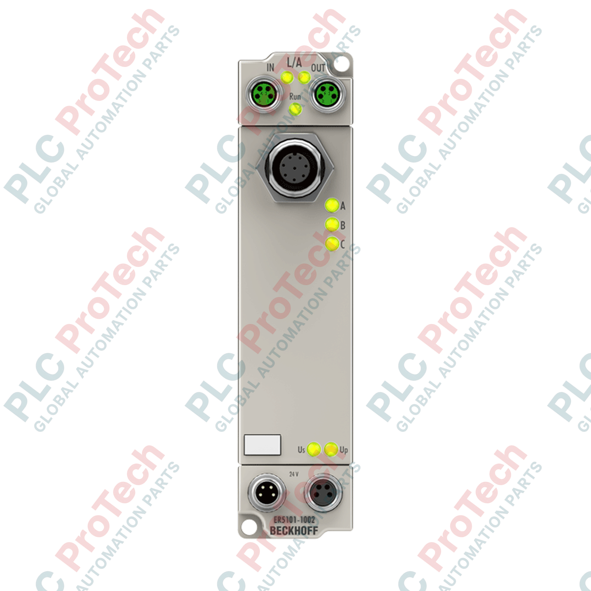
Engineered for direct field integration without an electrical cabinet, the Beckhoff ER5101-1002 provides a high-performance 1-channel incremental encoder interface within a ruggedized, fieldbus-independent EtherCAT Box architecture. This robust module enables direct reading of RS422 differential signals, TTL single-ended inputs, or pulse-train generators to enable precise real-time positioning and speed tracking. Encased in a heavy-duty zinc die-cast housing, the device offers complete IP67 protection, making it ideal for severe industrial environments subject to high humidity, moisture, and dust contamination.
Features
-
Versatile Encoder Interface: Supports standard RS422 differential signals (A, A_inv, B, B_inv, C, C_inv) and single-ended TTL signals.
-
High-Speed Processing: Up to 4 million increments per second (4 MHz limit frequency) via integrated 4-fold quadrature evaluation.
-
Flexible Counter Depth: Configurable 16-bit or 32-bit binary counter with zero-pulse latch capabilities.
-
Distributed Clocks: Highly synchronized time-stamping via integrated EtherCAT Distributed Clocks (DC) support.
-
Integrated Sensor Supply: On-board 24 V DC sensor power supply rated up to 500 mA, protected against short circuits.
-
Harsh Environment Protection: Zinc die-cast enclosure meeting IP65, IP66, and IP67 specifications.
Applications
-
Decentralized Motion Tracking: Precise positioning on dynamic machine axes without cabinet routing.
-
Conveyor and Sorting Lines: Direct motor shaft or conveyor speed feedback using rotary incremental encoders.
-
Washdown & Wet Processing Areas: Deployable on food processing, packaging, and chemical production machinery.
-
Outdoor Material Handling: Reliable operation in crane controls, wind energy yaw systems, and utility assets.
Technical Specifications
| Specification Parameter |
Value / Rating |
| Manufacturer |
Beckhoff Automation |
| Model Number |
ER5101-1002 |
| Signal Interface |
1-channel incremental encoder (A, B, C / RS422, TTL) |
| Max. Input Frequency |
4,000,000 increments/s (with 4-fold evaluation) |
| Nominal System Voltage |
24 V DC (-15% / +20%) |
| Encoder / Sensor Supply |
24 V DC, max. 500 mA (VCC) |
| Internal Counter |
16-bit or 32-bit binary |
| Transmission Rate |
100 MBaud (EtherCAT) |
| Bus Connection Interfaces |
2 x M8 socket, shielded, screw type |
| Power Feed Interfaces |
Feed: 1 x M8 male (4-pin); Downstream: 1 x M8 female (4-pin) |
| Current Consumption (US) |
Typ. 130 mA + sensor load |
| Electrical Isolation |
500 V |
| Enclosure Protection |
IP65 / IP66 / IP67 (conforms to EN 60529) |
| Operating Temperature |
0 to +55 degC |
| Storage Temperature |
-25 to +85 degC |
| Approvals & Markings |
CE, UL |
| Country of Origin |
Germany |
| Shipping Weight (Calculated) |
0.45 kg |
| Package Dimensions (Calculated) |
150 mm x 50 mm x 45 mm |
Connections and Interfaces
| Connection / M8 Pin |
Signal Designation |
Functional Assignment |
| Power Feed Pin 1 |
US (+24 V DC) |
Control voltage supply for internal electronics and sensor power |
| Power Feed Pin 2 |
UP (+24 V DC) |
Load voltage supply for downstream actuators/peripheral outputs |
| Power Feed Pin 3 |
GNDS |
Ground reference for control voltage (US) |
| Power Feed Pin 4 |
GNDP |
Ground reference for load voltage (UP) |
Empirical Engineering Insights
Alternative Models & Compatibility
The ER5101-1002 is functionally equivalent to the plastic-housed EP5101-0002 module. In high-vibration applications or environments containing aggressive machine coolants, migrating from the EP series to the zinc die-cast ER5101-1002 is highly recommended for enhanced physical durability. Always verify that the TwinCAT EtherCAT System Manager configuration imports the matching XML device description (ESI) specifically representing the hardware revision shown on the module label to prevent configuration mismatch and initialization errors.
Application Pitfalls & Engineering Notes
When deploying high-current encoders, monitor the cumulative sensor supply draw on the 24 V DC (VCC) line. The ER5101-1002 provides a maximum of 500 mA. If an optical encoder with high current demands or heaters is integrated, an external power feed should be used to avoid overloading the module's internal regulator. Additionally, when daisy-chaining power across multiple EtherCAT Boxes, ensure total current passing through the M8 power connectors does not exceed the absolute limit of 4 A per circuit.
Commissioning & Wiring Tips
To minimize electrical noise and ensure reliable pulse counts up to 4 MHz, use fully shielded twisted-pair cabling for the encoder lines. Ensure that the cable shield is cleanly connected to the M12 connector housing. For single-ended TTL encoders, configure the unused negative channel inputs (A inv, B inv, and C inv) via the TwinCAT CoE (CoE register 0x8000) to adjust internal threshold levels and prevent spurious pulse generation from floating inputs.
Installation Guidelines
CRITICAL WARNING: De-energize all system power supplies (US and UP) before connecting or disconnecting any M8 or M12 interfaces. Executing hot-plugs on these industrial connectors risks electric arcing, pin oxidation, and permanent destruction of the internal EtherCAT communication ASIC.
1
Mount the ER5101-1002 Box onto a flat, vibration-damped surface using two M3 screws through the integrated upper and lower mounting holes. Torque mounting hardware to 0.8 Nm.
2
Establish the EtherCAT connections utilizing shielded M8 cables. Hand-tighten the screw collars to secure IP67 environmental sealing.
3
Wire the encoder to the sensor port interface using M12 industrial cabling, ensuring the cable shield terminates cleanly onto the connector body.
4
Apply 24 V DC system power (US) and run a diagnostic scan via Beckhoff TwinCAT System Manager to initiate device parameter configuration.