Description
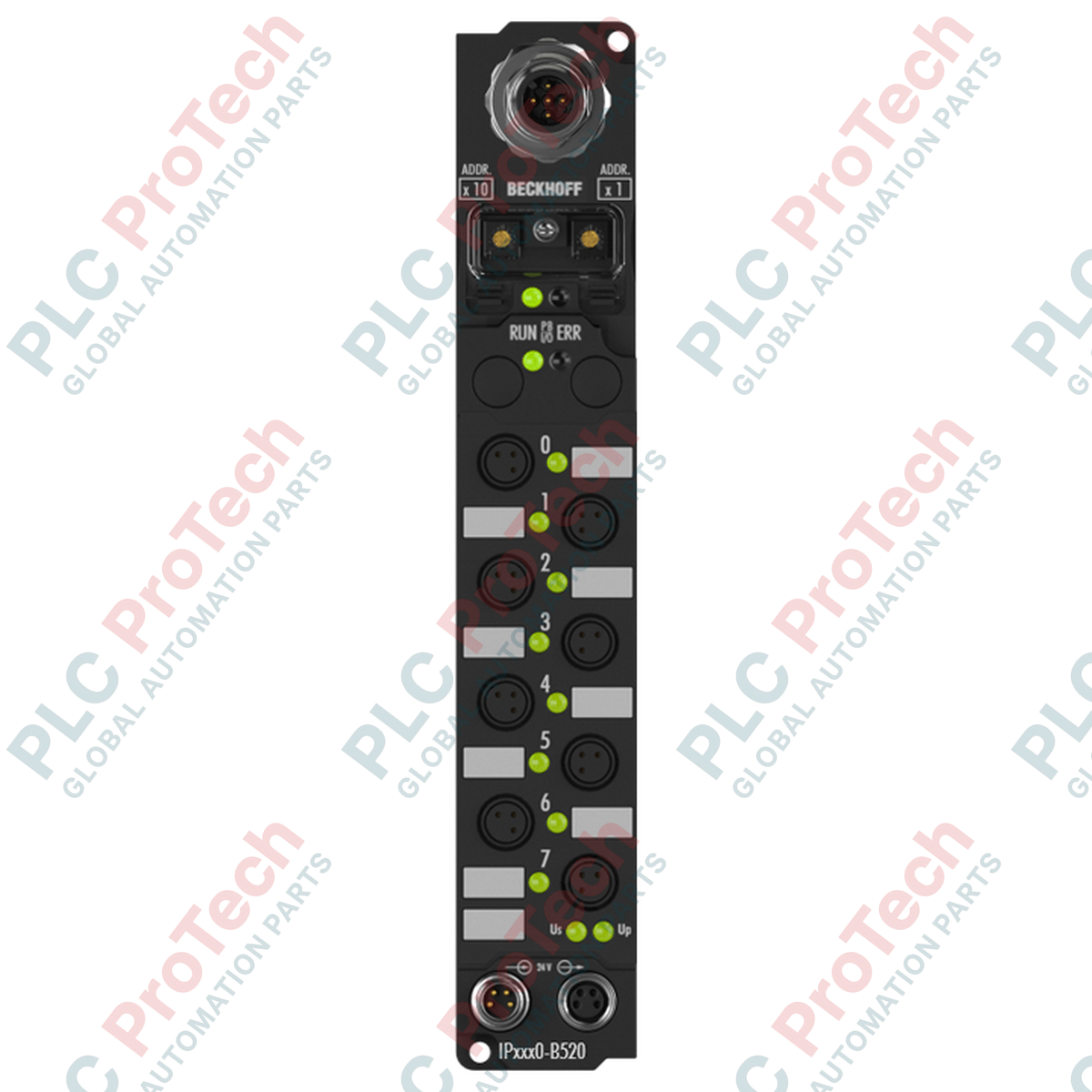
Facilitating robust decentralized control in harsh operating environments, the Beckhoff IP1000-B528 interfaces eight digital sensors directly with a DeviceNet network. This Fieldbus Box module eliminates the need for protective control cabinets by providing a highly ruggedized, machine-mountable form factor with integrated connection interfaces. It operates on a 24 V DC control voltage and processes signals with an input filter timing of 3 ms. Equipped with an integrated T-connector for the DeviceNet network, the module permits straightforward daisy-chain topologies directly on the machinery, minimizing cabling effort and transmission line losses.
Features
Applications
- Decentralized factory automation lines utilizing DeviceNet architectures.
- Material handling, packaging machinery, and assembly lines requiring field-mounted I/O blocks.
- Environments with high humidity, washdown requirements, or heavy particulate exposure.
Technical Specifications
| Specification Parameter |
Value / Rating |
| Manufacturer |
Beckhoff Automation |
| Model Designation |
IP1000-B528 |
| Fieldbus Protocol |
DeviceNet |
| Digital Inputs |
8 channels, 24 V DC, 3 ms filter time |
| Data Transfer Rates |
Auto-detection up to 500 kbaud |
| Bus Interface Connection |
1 x M12 plug (5-pin), 1 x M12 socket (5-pin) |
| Control Voltage Supply |
24 V DC (-15% / +20%) |
| Power Supply Feed |
1 x M8 male socket (4-pin) |
| Power Supply Downstream |
1 x M8 female socket (4-pin) |
| Internal Box Supply Current |
45 mA + sensor load (max. 0.5 A cumulative) |
| Electrical Isolation |
Control voltage to fieldbus: 500 V |
| Protection Rating |
IP65 / IP66 / IP67 (conforms to EN 60529) |
| Operating Temperature Range |
0 to +55 degC |
| Storage Temperature Range |
-25 to +85 degC |
| Standards Conformance |
EN 60068-2-6 (Vibration), EN 60068-2-27 (Shock), CE, UL |
| Country of Origin |
Germany |
| Shipping Weight (Calculated) |
2.0 kg |
Connections and Interfaces
| Connector / Port |
Interface Type |
Pin / Signal Mapping |
| Fieldbus Input (Upstream) |
M12 Male, 5-pin |
Pin 1: Shield, Pin 2: V+, Pin 3: V-, Pin 4: CAN_H, Pin 5: CAN_L |
| Fieldbus Output (Downstream) |
M12 Female, 5-pin |
Looped parallel connection (integrated T-connector) for drop-line routing |
| Power Supply Feed |
M8 Male, 4-pin |
Pin 1: Feed 24 V DC control voltage, Pin 3: GND control, Pin 2/4: Load voltage loops |
| Power Supply Downstream |
M8 Female, 4-pin |
Daisy-chain distribution to adjacent Fieldbus Box modules |
Empirical Engineering Insights
Alternative Models & Compatibility
The IP1000-B528 belongs to the classic Beckhoff Fieldbus Box architecture. If transitioning from older CANopen or PROFIBUS variants (e.g., IP1000-B510 or IP1000-B310), ensure the DeviceNet scanner card is updated with the correct EDS (Electronic Data Sheet) files specific to the -B528. This module can be substituted with IP1012-B528 variants depending on the sensor connection requirements (such as M12 inputs instead of M8), but internal mapping profiles remain functionally identical.
Application Pitfalls & Engineering Notes
When calculating current budgets, note that the sensor supply maxes out at 0.5 A. Exceeding this limit across the 8 digital inputs will cause internal overload recovery shutoffs. In high-vibration applications, ensure that all unused M8 and M12 ports are sealed with Beckhoff-approved protective caps to prevent moisture ingress from violating the IP67 pressure seal.
Commissioning & Wiring Tips
The integrated T-connector is a hardware-level convenience, but it does not contain built-in termination. If the IP1000-B528 is positioned at the physical end of the DeviceNet trunk, a dedicated 121-ohm external M12 termination resistor must be plugged into the downstream M12 socket. Use the KS2000 configuration interface to set precise node addresses before installing the modules in locations with limited physical access.
Installation Guidelines
CRITICAL WARNING: Completely de-energize the entire DeviceNet trunk and local power supplies prior to mounting or disconnecting interfaces. Connecting or disconnecting M8/M12 interfaces under load can cause electrical arcing, potential transceiver damage, and communication dropouts on the active network.
1
Mount the Fieldbus Box on a flat, vibration-resistant surface using two M4 bolts. Torque to specified structural limits without deforming the plastic housing.
2
Connect the incoming DeviceNet fieldbus cable to the 5-pin M12 male connector and, if needed, run the downstream loop from the 5-pin M12 female socket.
3
Plug the 24 V DC power supply feed into the 4-pin M8 male socket. Torque the knurled metal nut to ensure proper gasket sealing.
4
Attach sensor cables to the M8 digital input channels. Use protective blanking caps on any unused ports to guarantee IP67 integrity.