Description
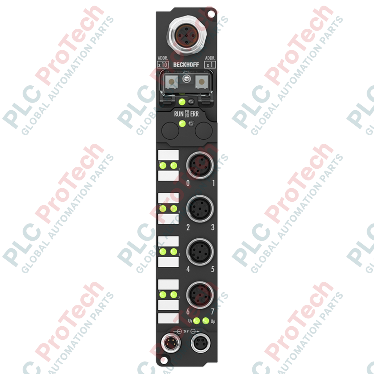
Decentralized digital signal acquisition in harsh production environments is managed via the Beckhoff IP1012-B730, a rugged IP67-rated Modbus fieldbus module featuring integrated screw-type connections. This distributed I/O device enables the direct acquisition of up to eight digital sensor signals near the process machinery, minimizing field cabling runs and reducing control cabinet footprint. Operating on the Modbus RTU/ASCII protocol over an RS485 transmission medium, it supports adjustable data transfer rates from 150 to 38,400 baud. Built with a high-durability polyamide housing, this fieldbus box is optimized for industrial installations requiring resistance to wet, dusty, or high-vibration environments without requiring an additional protective enclosure.
Features
-
8 Digital Inputs: Accommodates standard 24 V DC sensors with an integrated 0.2 ms input filter to suppress signal contact bounce.
-
Modbus RTU/ASCII Interface: Multi-drop RS485 physical layer with a highly configurable address range using physical rotary switches.
-
Sub-Millisecond Response: Exceptionally fast internal processing with a tight 0.2 ms signal propagation and filtering pipeline.
-
Industrial Protection Class: Certified IP65, IP66, and IP67 ingress protection, safeguarding internal electronics against dust and direct water jets.
-
Robust M12/M8 Connections: Standardized thread connections ensure gas-tight, vibration-proof electrical contacts under extreme structural strain.
Applications
-
Conveyor and Material Handling Systems: Direct mounting on transport rails for proximity sensor, photoelectric gate, and limit switch integration.
-
Automotive Assembly Lines: Decentralized pneumatic valve monitoring and tooling sensor tracking in high-vibration robotic work cells.
-
Packaging and Food Processing Machinery: Splash-resistant field I/O placement for washdown-tolerant wash steps and sorting systems.
-
Municipal Water & Infrastructure: Distributed remote telemetry units for flow switches, pressure alerts, and valve status reporting over RS485.
Technical Specifications
| Parameter |
Specification Value |
| Manufacturer |
Beckhoff Automation |
| Model Reference |
IP1012-B730 |
| Protocol Support |
Modbus RTU / Modbus ASCII |
| Data Transfer Rates |
150, 300, 600, 1200, 2400, 4800, 9600, 19200, 38400 baud |
| Number of Digital Inputs |
8 channels |
| Nominal Input Voltage |
24 V DC (-15% / +20%) |
| Input Filter Time |
0.2 ms |
| "0" Signal Voltage |
-3 to +5 V DC (EN 61131-2, Type 2) |
| "1" Signal Voltage |
11 to 30 V DC (EN 61131-2, Type 2) |
| Input Current |
Typical 6 mA per channel (EN 61131-2, Type 2) |
| Sensor Power Supply |
Max 0.5 A total (short-circuit proof) derived from control voltage |
| Power Supply Connections |
1 x M8 male socket (4-pin feed), 1 x M8 female socket (4-pin downstream) |
| Box Current Consumption |
45 mA (excluding sensor current load) |
| Electrical Isolation |
Control voltage to fieldbus: Yes; Channels to control voltage: No |
| Vibration / Shock Resistance |
Conforms to EN 60068-2-6 / EN 60068-2-27 |
| Operating Temperature Range |
0 to +55 degC |
| Storage Temperature Range |
-25 to +85 degC |
| Housing Material |
PA6 (Polyamide), non-reinforced |
| Physical Dimensions |
30 mm x 175 mm x 26.5 mm (W x H x D) |
| Mounting Options |
2 x 3.5 mm diameter fixing holes for M3 structural fasteners |
| Country of Origin |
Germany |
| Shipping Weight (Calculated) |
2.0 kg (including export transit protective packaging) |
Connections and Interfaces
| Port Reference |
Connector Type |
Pin / Wire Allocation & Function |
| Bus Interface |
1 x M12 socket, 5-pin, B-coded |
Modbus RS485 communication lines (TxD/RxD-A, TxD/RxD-B, Shield connection) |
| Digital Inputs (0-7) |
8 x M12 screw type |
M12 input sockets mapping directly to 8 process image bits. Dedicated sensor voltage feed. |
| Power Feed |
1 x M8 male connector, 4-pin |
Primary 24 V DC control voltage (Us) and peripheral load voltage (Up) supply input |
| Power Downstream |
1 x M8 female connector, 4-pin |
Daisy-chain pass-through routing of Us and Up to subsequent downstream Fieldbus Box modules |
Empirical Engineering Insights
Alternative Models & Compatibility
The IP1012-B730 belongs to the legacy Beckhoff Modbus RTU product line. When migrating or integrating this hardware into newer EtherCAT structures, you can use the EK1100 coupler combined with EL1008 terminals as an in-cabinet equivalent. If a direct IP67 field-mount form factor is required under an EtherCAT architecture, the EP1008-0002 serves as a drop-in physical equivalent, though it requires re-routing the communications protocol from Modbus RTU to EtherCAT.
Application Pitfalls & Engineering Notes
A common failure point in wet-field installations is localized internal condensation. While the PA6 polyamide housing holds an IP67 rating, this is only true if all unused M12 and M8 ports are sealed with industrial-grade protective caps tightened to the specified torque. Unprotected open threads will allow moisture ingress under temperature cycles due to pressure equalization, which can lead to premature logic-side failures.
Commissioning & Wiring Tips
When configuring the Modbus node address, ensure that you adjust the built-in rotary switches prior to powering up the system; the IP1012-B730 only reads the hardware switch address during the initial boot sequence. If using long RS485 trunk lines (approaching the 1200-meter maximum), always install an external 120-Ohm terminal resistor on the final downstream device's B-coded M12 interface to prevent signal reflections and packet collision errors.
Installation Guidelines
CRITICAL SAFETY WARNING
Disconnect all primary control voltage and secondary load power sources before terminating or servicing any physical connectors. High transient fields or live connection actions can cause terminal arc flashover, disrupting the local communication bus and leading to potential hardware degradation on adjacent field devices. Verify zero voltage potential with an electrical tester prior to maintenance.
1
Position the fieldbus box on a flat mounting surface and secure it using two M3 bolts through the pre-drilled 3.5 mm structural mounting eyelets. Apply a maximum tightening torque of 0.8 Nm to prevent cracking the polyamide housing.
2
Set the network ID by removing the protective screw cap covering the rotary address switches. Carefully set the desired Modbus node value, then re-secure the cap tightly to maintain the IP67 physical rating.
3
Connect the B-coded M12 fieldbus cable to the dedicated network socket. For the final network node on the RS485 loop, install a dedicated 120-Ohm M12 termination plug.
4
Wire the M8 power connectors. Terminate the male feed connector first, followed by the downstream daisy-chain connector if cascading multiple modules. Keep total sensor current below the 0.5 A threshold.