Description
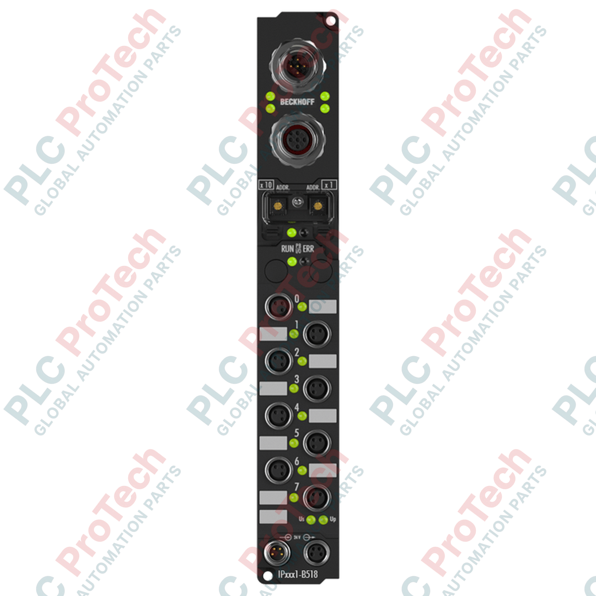
Engineered for decentralized automation architectures, the Beckhoff IP2001-B518 establishes direct, field-level digital actuation via the CANopen protocol. This high-density, IP67-rated Fieldbus Box permits the direct connection of up to eight digital actuators to a high-speed CAN network, negating the need for protective electrical enclosures. Each of the eight outputs delivers up to 0.5 A at 24 V DC, making it suitable for driving solenoid valves, contactors, indicators, and small DC motors under demanding ambient environments.
Features
-
8 Digital Outputs: Standard 24 V DC switching logic with individual short-circuit protection.
-
Direct CANopen Integration: Built-in node management supporting life/node guarding, emergency objects, and variable PDO mapping.
-
Integrated T-Connector: Dual M12 fieldbus interfaces simplify daisy-chaining without external junction blocks.
-
Submersible Enclosure: Encapsulated PA6 polyamide housing rated for IP65, IP66, and IP67 protection zones.
-
Compact M8 Actuator Ports: Space-optimized termination for industrial sensors and actuator cables.
Applications
- Machine-mount control systems omitting local terminal boxes.
- Material handling systems and modular conveyor networks.
- Pneumatic valve manifold control in food processing and packaging machinery.
- Mobile equipment and material transport systems utilizing CANopen system buses.
Technical Specifications
| Parameter |
Specification Value |
| Manufacturer |
Beckhoff Automation GmbH & Co. KG |
| Model Number |
IP2001-B518 |
| Fieldbus Protocol |
CANopen (up to 16 send/receive PDOs) |
| Baud Rate Detection |
Automatic: 10 kbaud to 1 Mbaud |
| Number of Outputs |
8 digital outputs |
| Output Voltage |
24 V DC (-15% / +20%) |
| Maximum Output Current |
0.5 A per channel (individually short-circuit proof) |
| Short-Circuit Current Limit |
Typical 1.5 A |
| Bus Interface Connectors |
1 x M12 plug (5-pin), 1 x M12 socket (5-pin) integrated T-connector |
| Power Supply Connection |
Feed: 1 x M8 male (4-pin); Downstream: 1 x M8 female (4-pin) |
| Internal Current Consumption |
45 mA from Us + sensor load (max 0.5 A) |
| Isolation Voltage |
500 V (Control voltage to fieldbus logic) |
| Ingress Protection Rating |
IP65 / IP66 / IP67 (conforming to EN 60529) |
| Operating Temperature |
0 to +55 degC |
| Storage Temperature |
-25 to +85 degC |
| Housing Material |
PA6 Polyamide |
| Dimensions (W x H x D) |
30 mm x 210 mm x 26.5 mm |
| Country of Origin |
Germany |
| Shipping Weight (Calculated) |
2.0 kg |
Connections and Interfaces
| Connector Type |
Pin Allocation |
Signal Assignment |
| M12 CANopen Bus (Plug/Socket) |
Pin 1 |
CAN Shield / PE |
| Pin 2 |
V+ (CAN Bus Power Supply) |
| Pin 3 |
V- (CAN Bus Reference Ground) |
| Pin 4 |
CAN_H (Signal High) |
| Pin 5 |
CAN_L (Signal Low) |
| M8 Power Feed (4-Pin Male) |
Pin 1 |
+24 V DC Control Voltage (Us) |
| Pin 2 |
+24 V DC Load Voltage (Up) |
| Pin 3 |
GND Control (GNDs) |
| Pin 4 |
GND Load (GNDp) |
Alternative Models & Compatibility
The IP2001-B518 is fully compatible with the Beckhoff KS2000 configuration software for parameterization and monitoring. When replacing legacy IP2001-B510 modules, verify standard network address switch settings and register maps, as the B518's integrated T-connector structure limits the need for external network splitting hardware.
Application Pitfalls & Engineering Notes
While the module features a total load-handling capacity of up to 4 A across all 8 channels, total heat dissipation within highly confined non-ventilated spaces must be modeled carefully. Additionally, when switching highly inductive loads, such as large pneumatic solenoid coils, external suppressor circuits or free-wheeling diodes should be placed at the load to protect the internal short-circuit monitoring circuitry from inductive kickback transients.
Commissioning & Wiring Tips
Always ensure that the CANopen network is terminated with 120-Ohm resistors at both physical endpoints of the trunk line. Use high-quality, shielded copper twisted-pair cabling for connection to the integrated M12 T-connector interface to avoid data frame corruption in environments with heavy variable frequency drive (VFD) interference.
Installation Guidelines
CRITICAL WARNING:
De-energize all primary system power loops (Us and Up) before inserting, removing, or wiring the Fieldbus Box. Failure to remove supply lines can trigger catastrophic bus controller faults or damage the short-circuit protection profiles of the outputs.
1
Mount the housing to a rigid surface using the two integrated 3.5 mm diameter fixing holes designed for M3 screws.
2
Route the CANopen bus topology through the integrated M12 T-connector, confirming secure hand-tightening of mating connectors to preserve the IP67 seal rating.
3
Connect the 4-pin M8 power feed cable. Ensure separation of control logic voltage (Us) and output load voltage (Up) lines if diagnostic separation is required.