Description
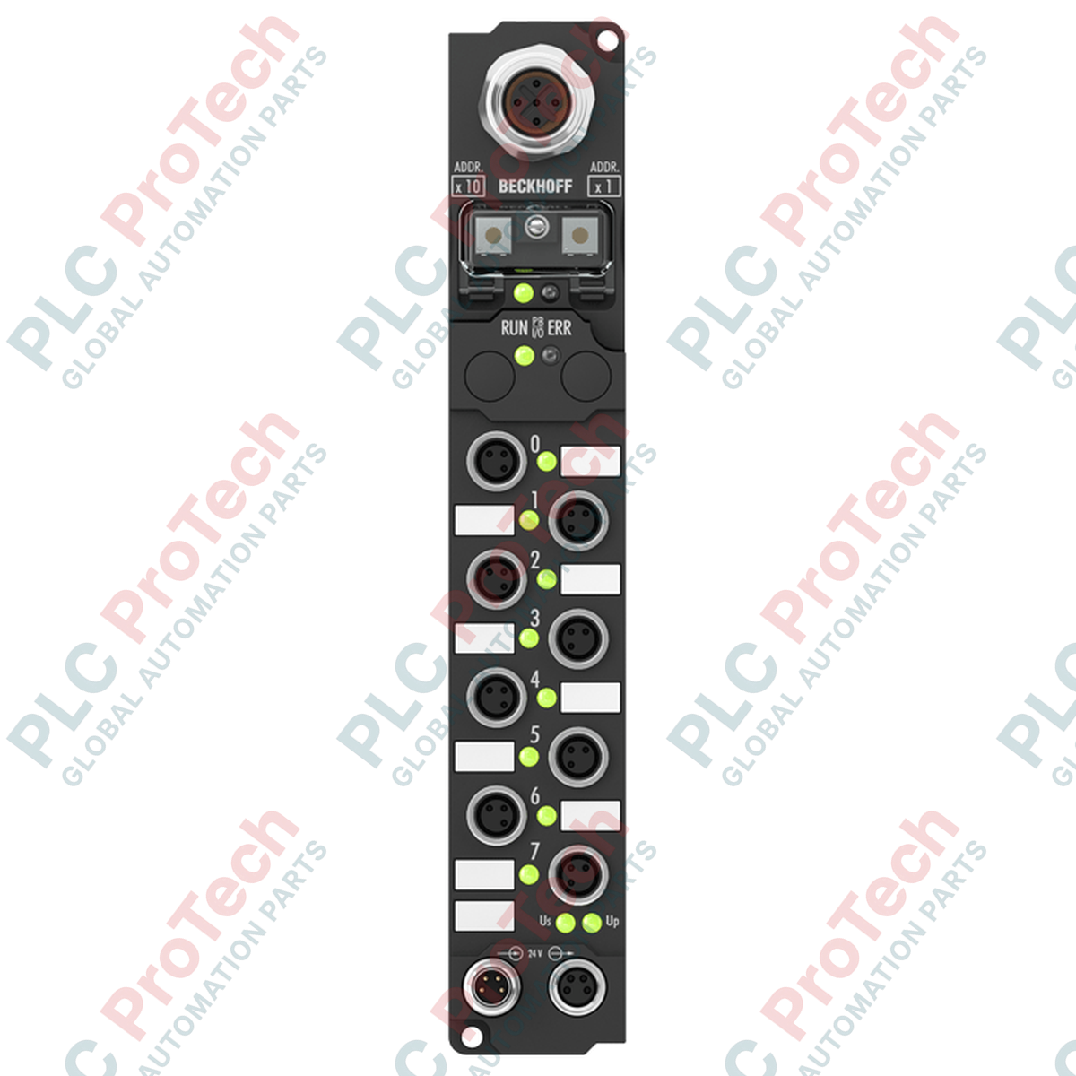
Designed for decentralized industrial automation, the Beckhoff IP2021-B730 is a rugged fieldbus module that interfaces eight digital outputs directly within hostile environments via the Modbus RTU/ASCII protocol. This unit eliminates the need for protective control cabinets by integrating an IP67-rated polyamide enclosure, making it ideal for distributed mounting directly onto machinery and processing systems. With M8 screw-type connections for outputs and a robust M12 RS485 communication interface, it ensures high signal integrity and rapid integration into existing Modbus networks.
Features
- Eight independent 24 V DC digital outputs rated for up to 2 A per channel.
- Each output channel is individually short-circuit proof to protect field wiring and connected loads.
- Direct Modbus RTU/ASCII protocol communication over RS485 physical layer.
- Address configuration selectable via onboard rotary switches or KS2000 software interface.
- IP65, IP66, and IP67 protection class rating for reliable performance in washdown and wet industrial areas.
- Diagnostic LEDs for localized troubleshooting of channel status, bus activity, and logic power.
Applications
- Decentralized control architectures in packaging and material handling lines.
- Direct machine actuation of solenoid valves, contactors, and small DC motors.
- Wet process areas, including food processing and wastewater treatment plants.
- Conveyor system routing and automated sorting mechanisms.
Technical Specifications
| Parameter |
Value |
| Manufacturer |
Beckhoff |
| Model Number |
IP2021-B730 |
| Product Type |
Fieldbus Box |
| Number of Outputs |
8 |
| Output Connections |
M8, screw type |
| Nominal Output Voltage |
24 V DC (-15 % / +20 %) |
| Max. Output Current |
2 A per channel (individual short-circuit proof, total sum max 4 A) |
| Protocol |
Modbus RTU / Modbus ASCII |
| Bus Interface |
1 x M12 socket, 5-pin, B-coded |
| Data Transfer Rates |
150, 300, 600, 1200, 2400, 4800, 9600, 19200, 38400 baud |
| Power Supply Connection |
Feed: 1 x M8 male socket (4-pin); Downstream: 1 x M8 female socket (4-pin) |
| Current Consumption from Us |
45 mA + sensor current (max. 0.5 A) |
| Process Image Bit Width |
8 outputs |
| Operating Temperature |
0 to 55 degC |
| Storage Temperature |
-25 to 85 degC |
| Protection Class |
IP65 / IP66 / IP67 (conforms to EN 60529) |
| Housing Material |
PA6 (polyamide) |
| Dimensions (W x H x D) |
30 mm x 175 mm x 26.5 mm |
| Weight |
approx. 210 g |
| Shipping Weight (Calculated) |
2.0 kg |
| Approvals |
CE, UL |
Empirical Engineering Insights
Alternative Models & Compatibility
The IP2021-B730 operates as a standalone Modbus slave node and does not support IP-Link extension modules (denoted by the extension module parameter omission in OEM documentation). If downstream expansion is required, consider moving to the IL230x series coupling modules.
Application Pitfalls & Engineering Notes
While each channel is capable of switching a 2 A load, the cumulative current limit across all eight channels is capped at 4 A total due to the thermal dissipation limits of the compact, sealed polyamide housing. Driving multiple inductive or lamp loads near the 2 A peak simultaneously will cause thermal overload, triggering the internal electronic circuit protection.
Commissioning & Wiring Tips
Any changes made to the rotary address selection switches will not register dynamically. A full system power cycle (disconnecting and reconnecting both the logic supply Us and auxiliary/load supply Up) is mandatory for the hardware to initialize the new Modbus address.
Installation Guidelines
CRITICAL WARNING: De-energize all primary, control, and auxiliary load power supplies before mounting, connecting, or servicing the module. Failure to fully isolate external 24 V DC pathways can cause permanent hardware damage, unexpected terminal shorting, or field hazard conditions during installation.
1
Mount the Fieldbus Box using the two pre-molded 3.5 mm diameter fixing holes on a flat surface using M3 bolts, ensuring the module is not subject to structural twisting.
2
Configure the Modbus station address on the rotary selection switches prior to cabling.
3
Connect the RS485 bus network line to the B-coded, 5-pin M12 socket, ensuring proper shield termination to eliminate communication noise.
4
Plug in the M8 power cables for control voltage logic (Us) and output load voltage feed. Tighten all connectors to the recommended torque specifications to maintain the IP67 environmental seal.