Description
Operating directly within the Beckhoff I/O system, the Beckhoff KS3681 Bus Terminal delivers high-precision electrical measurement capabilities in a compact terminal block form factor. This digital multimeter terminal measures DC and AC voltages up to 300 V and currents up to 10 A with an exceptional 18-bit resolution plus sign. Unlike standard KL-series terminals, the KS3681 features a pluggable wiring level, enabling fast hot-swapping during maintenance without disconnecting the terminal's field wiring. Integrated automatic range selection, true RMS calculation for AC waveforms, and arithmetic averaging for DC signals make this module suitable for direct integration into machine control architectures.
Features
-
Pluggable Wiring Level: Toolless terminal installation and rapid replacement using the pluggable KS connection system.
-
Multi-Range Capabilities: Measures voltage ranges from 300 mV to 300 V and current ranges from 100 mA to 10 A.
-
Dual Measuring Modes: Arithmetic averaging for DC signals and true RMS calculation for accurate AC measurements.
-
High Resolution & Accuracy: 18-bit plus sign resolution with a low 0.01% measuring error for DC voltage at 25 degC.
-
Electrical Isolation: 1500 V galvanic isolation between the K-bus and the field potential for reliable noise immunity.
-
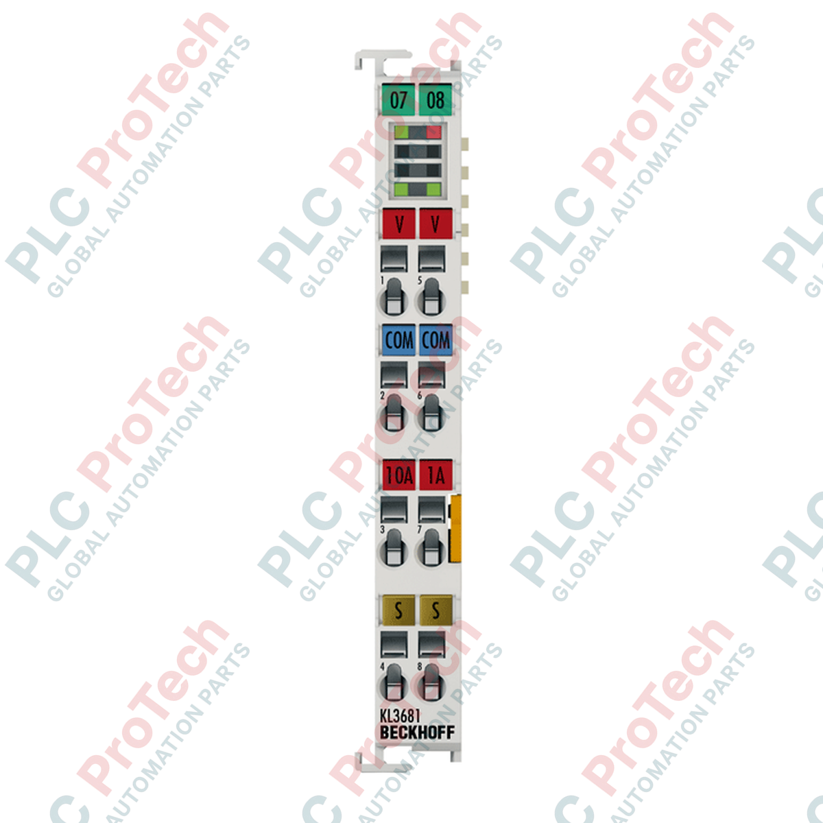
Integrated Protection: Equipped with a pre-installed 1.25 A fuse along with an onboard spare fuse.
Applications
- Direct voltage and current monitoring inside industrial control panels.
- Automatic test equipment (ATE) and quality control test benches.
- Power management and load verification in automated machinery.
- Grid and system-level diagnostics without external measuring transducers.
Technical Specifications
| Parameter |
Value / Specification |
| Manufacturer |
Beckhoff |
| Model Number |
KS3681 |
| Module Type |
Pluggable Digital Multimeter Bus Terminal |
| Number of Inputs |
1 voltage or 1 current input |
| Voltage Ranges |
300 mV, 3 V, 30 V, 300 V |
| Current Ranges |
100 mA, 1 A, 10 A (high current path) |
| Internal Resistance |
3 mOhm / 0.2 Ohm / 12.5 MOhm |
| Resolution |
18 bit + sign |
| Measuring Error |
0.01% for DC voltage measurement at 25 degC |
| Measuring Procedure |
DC with arithmetic averaging, AC with true RMS value calculation |
| Update Time |
0.5 s (1 s for automatic measuring range selection) |
| Current Consumption K-Bus |
typ. 100 mA |
| Current Consumption Power Contacts |
None (no power contacts utilized) |
| Process Image Bit Width |
32 bit data, 8 bit control/status |
| Electrical Isolation |
1500 V (K-bus to field potential) |
| Enclosure Material |
Polycarbonate |
| Operating Temperature |
0 to +55 degC (no condensation) |
| Relative Humidity |
95%, non-condensing |
| IP Rating |
IP20 |
| Dimensions (W x H x D) |
12 mm x 100 mm x 68 mm |
| Weight |
0.07 kg (70 g) |
| Shipping Weight (Calculated) |
2.0 kg |
Empirical Engineering Insights
Alternative Models & Compatibility
The KS3681 offers direct, drop-in functional equivalence to the standard KL3681 multimeter terminal. The primary differentiator is the KS design, which features a pluggable terminal connector block. Standard KL3681 modules require disconnecting every individual wire for terminal replacements. When migrating a system from KL3681 to KS3681, there is no change required to the TwinCAT software configuration, K-bus mapping, or register structure. The process image size remains identical at 32-bit data and 8-bit control/status.
Application Pitfalls & Engineering Notes
When utilizing the high-current path (up to 10 A), thermal behavior within dense enclosures must be monitored closely. Constant execution at 10 A can raise adjacent terminal ambient temperatures. It is recommended to mount the KS3681 with adequate lateral clearance or away from heat-generating components like terminal power feeds if high-current loads are active for extended durations. Note that the 1.25 A fuse only protects the standard current measurement circuits. Passing currents above 10 A through the high-current path will result in permanent damage to the internal shunt resistors.
Commissioning & Wiring Tips
To maintain the 0.01% measurement accuracy, always run shielded cables for your measurement leads, grounding the shield at the terminal assembly panel entry point. For the pluggable connections, use a standard slot screwdriver to actuate the tension clamps. Ensure wires are stripped exactly 9 to 10 mm. When utilizing automatic range selection, be aware of the 1-second update delay required for internal scaling circuitry to stabilize. If your application demands high-speed, deterministic sampling, configure the terminal for manual range selection via the TwinCAT System Manager control byte.
Installation Guidelines
CRITICAL WARNING
Disconnect all power sources from both the K-bus controller and the field measurement circuits before inserting, removing, or wiring the module. High-voltage potentials up to 300 V AC/DC may be present on measurement contacts, posing a severe electric shock hazard. Verify field-side circuits are fully de-energized with a calibrated external meter prior to handling the terminal block assembly.
1
Mount the terminal on a standard 35 mm DIN rail conforming to EN 60715, securing it firmly until the locking mechanism clicks into place.
2
Align the lateral tongue-and-groove connections carefully with adjacent K-bus terminals to prevent damage to the gold-plated slide contacts.
3
Wire the pluggable terminal connector block using a flat-head screwdriver. Secure solid or stranded conductors (0.08 to 1.5 mm sq) into the spring clamp terminals.
4
Connect the pre-wired pluggable wiring block to the terminal face. Apply control voltage to verify the K-bus status LEDs illuminate correctly.