Description
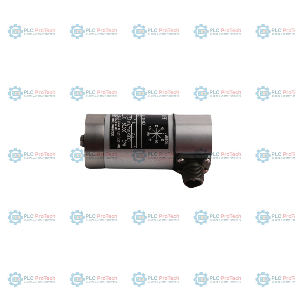
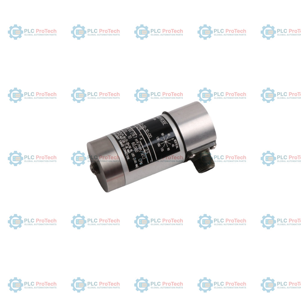
Le Bently Nevada 9200-01-02-10-00 est un transducteur de vitesse Seismoprobe à deux fils conçu pour mesurer la vibration absolue du carter sur les machines tournantes. Ce transducteur à bobine mobile fournit une sortie en tension directement proportionnelle à la vitesse de vibration du carter de la machine. Il fonctionne sans alimentation externe, utilisant une conception auto-génératrice qui simplifie le câblage sur site et l'intégration dans les systèmes de surveillance continue. Le 9200-01-02-10-00 est généralement connecté aux systèmes de protection des machines, tels que la série Bently Nevada 3500, pour fournir un diagnostic continu des machines, une détection précoce des défauts et une évaluation des vibrations structurelles.
Caractéristiques
- Conception à bobine mobile auto-génératrice ne nécessitant aucune source d'alimentation externe.
- Configuration de connexion à deux fils minimisant la complexité du câblage.
- Haute sensibilité aux vibrations basse fréquence des carters de machines.
- Construction durable adaptée aux environnements industriels difficiles.
- Capacités de surveillance en ligne continue pour la vitesse structurelle et du carter.
Applications
- Surveillance des vibrations des carters de grandes machines tournantes
- Ventilateurs industriels, soufflantes et unités de traitement d'air
- Pompes centrifuges et compresseurs
- Diagnostic des carters de turbines à vapeur et à gaz
- Analyse structurelle des moteurs électriques et des boîtes de vitesses
Informations de commande
- 9200 : Transducteur de vitesse Seismoprobe à deux fils
- 01 : Version température standard
- 02 : Option de montage du transducteur
- 10 : Option fréquence minimale de fonctionnement
- 00 : Pas d'approbations pour zones dangereuses
Caractéristiques techniques
| Paramètre |
Spécification |
| Fabricant |
Bently Nevada |
| Pays d'origine |
États-Unis |
| Type de produit |
Transducteur de vitesse Seismoprobe |
| Sensibilité |
20 mV/mm/s (500 mV/in/s) plus ou moins 5 % à 100 Hz |
| Réponse en fréquence |
10 Hz à 1000 Hz plus ou moins 3 dB |
| Plage de température de fonctionnement |
-29 à +121 degrés Celsius (-20 à +250 °C) |
| Orientation de montage |
Orientation verticale ou horizontale selon l'option choisie |
| Matériau du boîtier |
Acier inoxydable |
| Type de connexion |
Câble intégré ou variante avec connecteur supérieur |
| Poids estimé |
Environ 0,30 kg |
| Dimensions |
Environ 41 mm de diamètre sur 102 mm de hauteur |
Connexions / interfaces
| Broche du connecteur |
Fonction |
| Broche A / fil rouge |
Signal positif (+) |
| Broche B / fil blanc |
Signal négatif (-) / commun |
| Protection |
Mise à la terre du boîtier / terminaison de la protection |
Directives d'installation
-
Alignement de l'orientation : Assurez-vous que le transducteur est monté exactement dans les limites d'orientation spécifiées (verticale ou horizontale) pour maintenir la précision indiquée.
-
Préparation de la surface : La surface de montage doit être plate, lisse, propre et serrée au couple selon les spécifications d'ingénierie recommandées pour assurer une transmission correcte de la fréquence.
-
Blindage et mise à la terre : Terminez le blindage du câble uniquement à la terre du châssis du système de surveillance. Ne connectez pas le blindage à l'extrémité du transducteur pour éviter les boucles de terre.
-
Cheminement des câbles : Faites passer les câbles du transducteur dans des conduits dédiés ou des chemins de câbles, à l'écart des lignes haute tension et des machines électriques lourdes pour réduire les interférences EMI/RFI.
-
Protection contre l'humidité : Appliquez un scellement environnemental approprié ou des protections étanches sur l'assemblage du connecteur lors d'une utilisation en milieu humide ou en extérieur.
FAQ
Quel est le principe de fonctionnement principal du transducteur ?
Il utilise un ensemble bobine mobile et aimant permanent qui génère une tension proportionnelle à la vitesse de la vibration physique sans alimentation électrique externe.
Ce modèle nécessite-t-il un pilote ou un émetteur de sonde de proximité externe ?
Non, c'est un capteur de vitesse auto-généré qui s'interface directement avec la carte de surveillance de traitement.
Que se passe-t-il si un transducteur vertical est monté horizontalement ?
L'ensemble ressort-masse interne se désalignera, provoquant des frottements internes, des lectures inexactes et des dommages potentiels à la suspension de la bobine interne.
Comment le blindage du câble doit-il être terminé pour les installations sur site ?
Le blindage doit être isolé au niveau du boîtier du transducteur et connecté proprement à la terre de l'instrument à l'intérieur de l'armoire de surveillance.
Cette unité peut-elle être réparée sur site si le boîtier est endommagé ?
Non, le transducteur est une unité scellée en usine et doit être remplacé ou renvoyé au fabricant pour recalibrage et service.
Quelle est l'impédance de sortie typique de ce capteur ?
Il présente une conception à faible impédance de sortie, ce qui le rend adapté à la conduite de câbles de transmission longs sans dégradation significative du signal.
Une calibration est-elle nécessaire lors de l'installation initiale ?
L'appareil est calibré en usine et ne nécessite pas d'ajustement sur site, bien qu'une vérification périodique du paramètre de sensibilité soit recommandée.
Quelles sont les causes de distorsion ou de saturation du signal dans ce type de capteur ?
Des chocs mécaniques sévères dépassant les limites physiques de la suspension de masse interne peuvent provoquer un contact interne et une distorsion du signal.
Le transducteur peut-il être peint lors de la maintenance courante des machines ?
Il n'est pas recommandé de peindre le corps du capteur car cela peut retenir la chaleur, masquer les étiquettes d'identification et potentiellement gêner l'accouplement de la base de montage.
Comment la température ambiante affecte-t-elle la sensibilité de l'appareil ?
La sensibilité reste très stable sur la plage de température de fonctionnement spécifiée, avec une légère variation prise en compte dans les données de vérification technique.