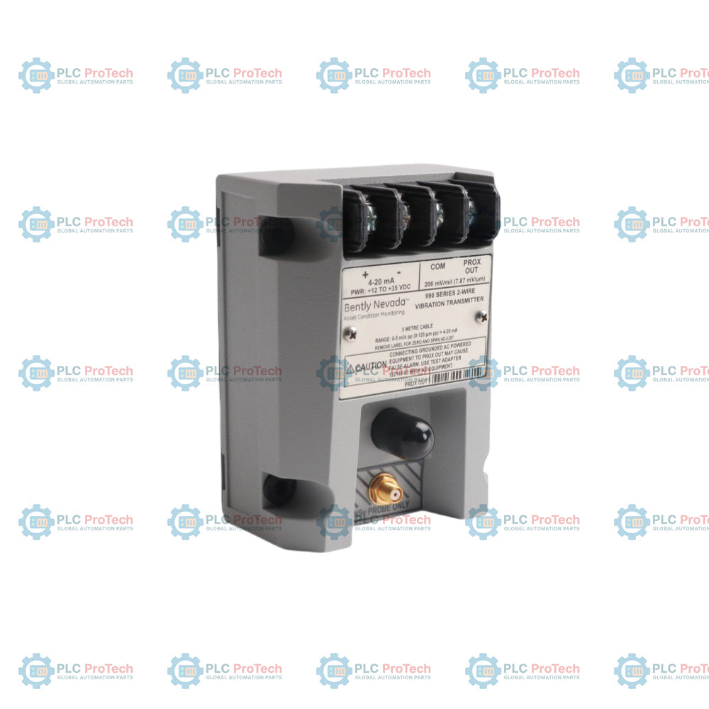
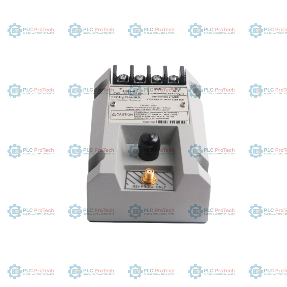
| Chemin d'entrée principal |
Accepte une sonde à courant de Foucault non contact 3300 NSv à canal unique et câble assorti |
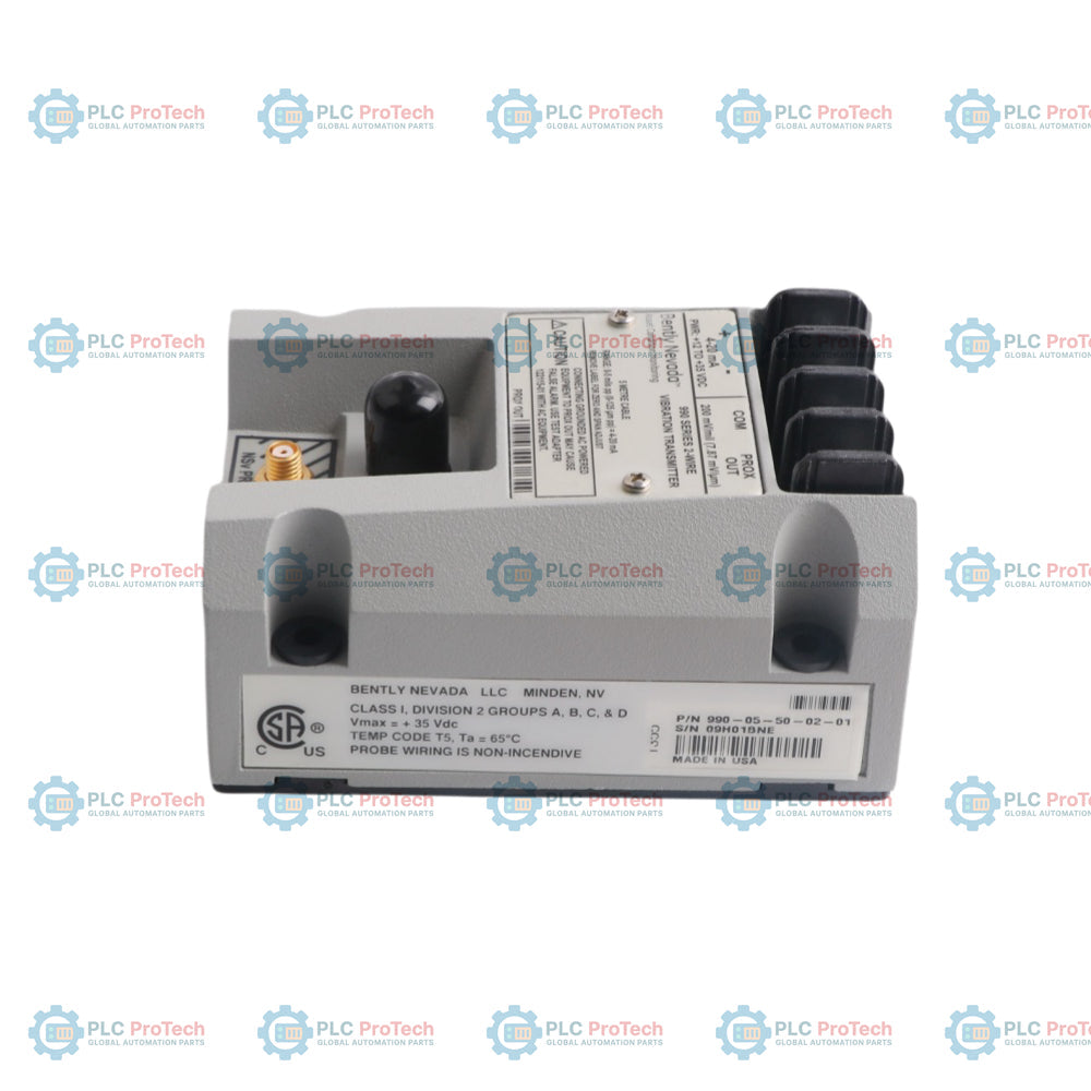
| Plage de tension d'alimentation |
Alimentation de +12 Vcc à +35 Vcc mesurée directement aux bornes du transmetteur |
| Signal de boucle de courant |
Configuration 2 fils fournissant 4 à 20 mAcc proportionnels au déplacement crête à crête |
| Allocation d'erreur de boucle |
Dans ±1,5 % de l'échelle complète sur une résistance de boucle de surveillance standard de 250 ohms |
| Écart de proximité de la cible |
Écart d'installation mécanique entre 0,5 et 1,75 mm (20 et 55 mils) |
| Contraintes d'impédance |
Seuil maximal de résistance de boucle de 1 000 ohms à pleine alimentation de 35 Vcc |
| Seuil de surintensité |
Limité en interne à un maximum typique de 23 mA |
| Action de sécurité en cas de défaillance de boucle |
La sortie chute en dessous de 3,6 mA dans les 100 microsecondes suivant une faute de sonde ou de connexion |
| Fenêtre de récupération après faute |
Restaure le suivi analogique normal dans les 2 à 3 secondes après la suppression d'une faute |
| Stabilisation à la mise sous tension |
La sortie chute en dessous de 3,6 mA pendant 2 à 3 secondes lors de la montée en puissance initiale du système |
| Impédance dynamique du port |
Impédance de source calibrée de 10 kohms configurée spécifiquement pour une charge de test de 10 Mohms |
| Champ linéaire du capteur |
Plage totale de 1,4 mm (55 mils) débutant à 0,25 mm (10 mils) de la surface cible |
| Performance du facteur d'échelle |
7,87 mV/micromètre (200 mV/mil) ±6,5 % typique basé sur une cible en acier AISI 4140 |
| Plancher de bruit inhérent |
Niveau de bruit typique de 50 mV crête à crête |
| Déviation de la dérive thermique |
Le facteur d'échelle reste dans ±10 % de la valeur nominale de 0 °C à +70 °C (+32 °F à +158 °F) |
| Bande passante en fréquence |
Réponse plate de 5 Hz à 6 000 Hz avec courbes d'atténuation +0, -3 dB |
| Profilage minimum de la cible |
Diamètre minimum de la surface cible de 9,5 mm (0,375 po) |
| Limite du câble de diagnostic |
Distance maximale de câble physique de 3 mètres (10 pieds) pour la connexion coaxiale BNC |
| Limites ambiantes du transmetteur |
Fonctionnement : -35 °C à +85 °C ; stockage : -52 °C à +100 °C |
| Température du transducteur |
Limites de fonctionnement et de stockage de -52 °C à +177 °C |
| Métriques de masse matérielle |
Unité transmetteur : 0,43 kg (0,9 lbm) ; système total : typiquement 0,82 kg (1,8 lbm) |
| Composition de l'enveloppe |
Pointe du capteur : sulfure de polyphénylène (PPS) ; corps du boîtier : acier inoxydable AISI 303 ou 304 |
| Fabricant du produit |
Bently Nevada (une société Baker Hughes) |
| Origine de production |
États-Unis d'Amérique |